


8
ASSEMBLING
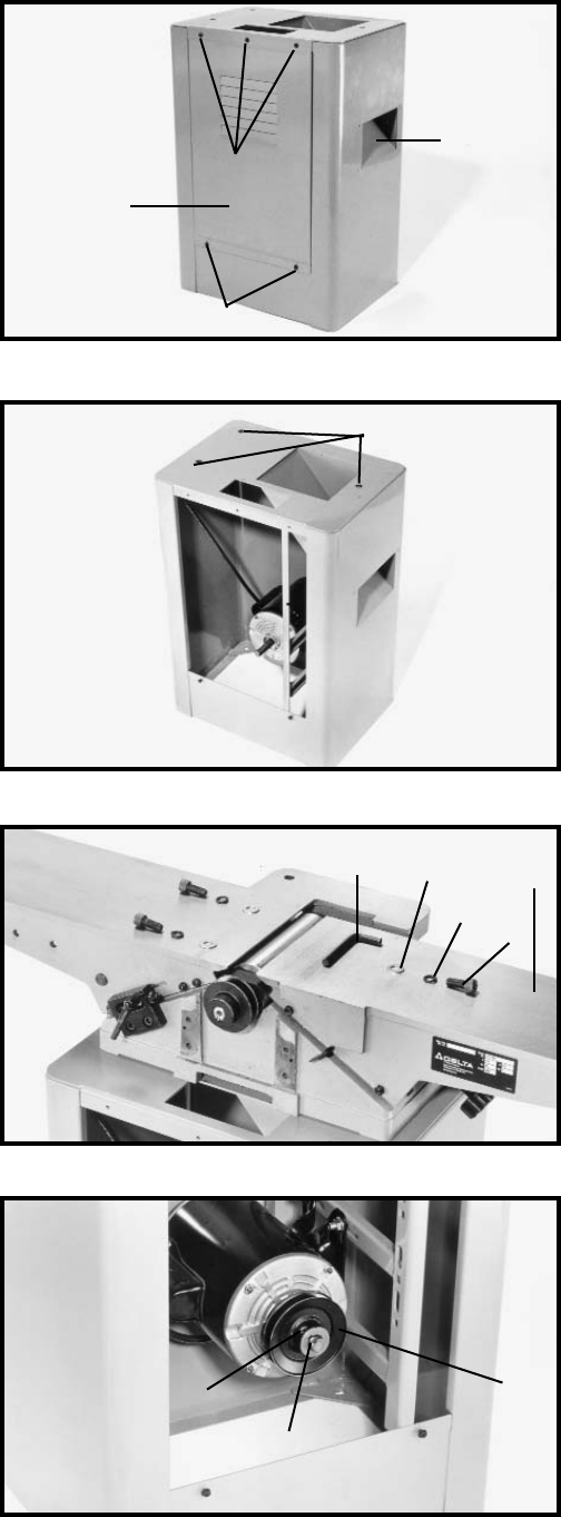
JOINTER TO STAND
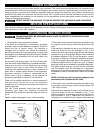
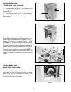
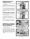
1. The outfeed end (N) Fig. 9, of the jointer must be
pointing toward the end of the stand with dust chute
opening (B) Fig. 7.
2. Remove three screws (C) Fig. 7, and loosen two
screws (D). Then remove back panel (E) from stand by
lifting upward.
Fig. 7
C
E
B
D
Fig. 8
F
Fig. 9
G
J
I
H
Fig. 10
L
M
K
3. Line up the three holes (F) Fig. 8, on the top of stand
with the three threaded holes on the bottom of the jointer
base. Using the supplied 8mm hex wrench (G) Fig. 9,
fasten the jointer to the stand. Place a M10.2
lockwasher (I), on a M10x1.5x20mm hex socket head
screw (H), and a M10 flat washer onto the screw. Insert
the screw through the hole in the stand and thread the
screw into the tapped hole in the bottom of the jointer,
and tighten securely. Repeat this process for the two
remaining holes in the stand and the jointer. NOTE: The
mounting hole located on the dust chute end of the
stand is accessed by reaching up through the dust
chute.
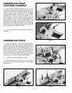
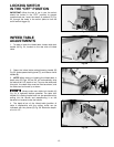
ASSEMBLING
MOTOR PULLEY
Assemble motor pulley (K) Fig. 10, to motor shaft with
the hub of the pulley in the outer position as shown.
Make certain key (L) is inserted in the keyway of the
pulley and motor shaft, then tighten set screw (M) using
the 2.5mm hex wrench (not shown).
N