


14
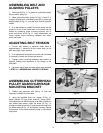
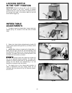
INFEED TABLE
POSITIVE STOPS
DISCONNECT MACHINE FROM
POWER SOURCE.
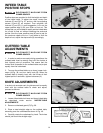
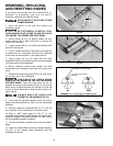
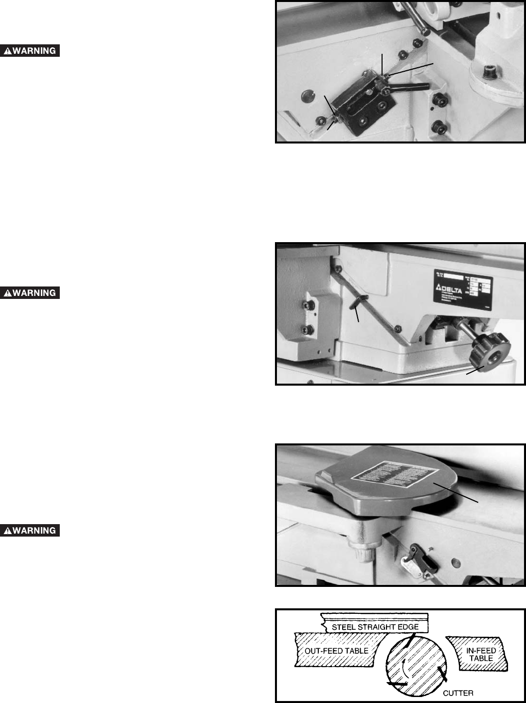
Positive stops are provided to limit the height and depth
of the infeed table. To adjust the stops, loosen two
locknuts (F) and (G) Fig. 37, and turn the two adjusting
screws (J) and (K) as required. Then retighten the
locknuts (F) and (G). A good suggestion is to set the
upper positive stop (J) for your finish or final cut. This
means that you will be able to rapidly set the infeed table
for a finish or final cut without checking the scale and
pointer. Also the lower positive stop (K) can be set for
the maximum depth-of-cut or if you desire to limit the
depth-of-cut, adjust the stop screw (K) accordingly.
Fig. 37
J
G
F
K
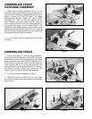
OUTFEED TABLE
ADJUSTMENTS
DISCONNECT MACHINE FROM
POWER SOURCE.
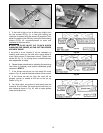
1. In order to perform accurate jointing operations, the
outfeed table must be exactly level with the knives at
their highest point of revolution. This means that the
knives must be parallel to the outfeed table and project
equally from the cutterhead.
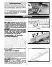
2. To move the outfeed table up or down, loosen lock-
screw (A) Fig. 38, and turn hand knob (B). When the
outfeed table is exactly level with the knives at their
highest point of revolution, tighten lockscrew (A).
Fig. 38
A
B
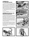
KNIFE ADJUSTMENTS
In order to do accurate work, the knives must be exactly
level with the outfeed table. To check and adjust,
proceed as follows:
DISCONNECT MACHINE FROM
POWER SOURCE.
1. Loosen infeed table lock lever and lower infeed table
as described under section “INFEED TABLE
ADJUSTMENTS”.
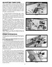
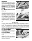
2. Remove cutterhead guard (C) Fig. 39.
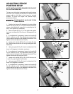
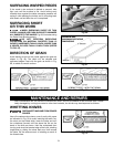
3. Place a steel straight edge on the outfeed table,
extending over the cutterhead as shown in Fig. 40.
4. Carefully rotate the cutterhead by hand. The knives
should just touch the straight edge.
Fig. 39
C
Fig. 40