6
Fig. 9
Fig. 10
Fig. 13
Fig. 12
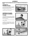
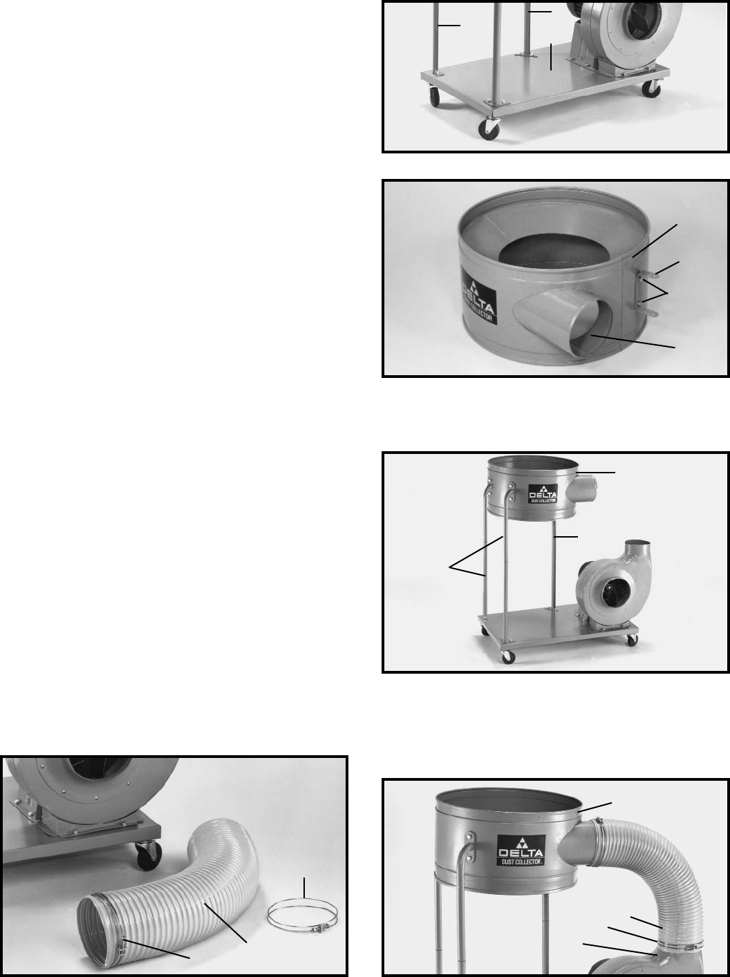
4. Assemble the remaining drum supports (F) Fig. 9, to
base (A) as shown.
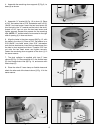
5. Assemble “U” bracket (H) Fig. 10, to drum (J). Place
a 5/16" flat washer then a 5/16" lockwasher onto a 5/16-
18x5/8" hex head screw. Insert the hex head screw (K)
thru the hole in the “U” bracket and the hole in the drum,
thread a 5/16" hex nut onto the hex head screw and
tighten securely. Repeat this process for the remaining
hole. NOTE: “U” bracket should be mounted to the right
side of opening (L) in drum as shown.
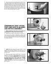
6. Align the holes in the drum support (M) Fig. 12, with
the holes in the drum (J). Place a 5/16" flat washer on a
5/16-18x5/8" hex head screw, then 5/16" lockwasher
onto the hex head screw, insert the hex head screw thru
the hole in drum support and drum. Thread a 5/16" hex
nut onto the hex head screw and tighten securely.
Fasten the remaining drum supports to the drum (J) in
the same manner.
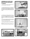
7. The dust collector is supplied with two 6" hose
clamps (P) Fig. 13. Place one end of 6" dia. flexible hose
(R) over blower/motor inlet (B) Fig. 14, and secure with
hose clamp (P).
8. Place the other 6" hose clamp on flexible hose and
attach the other end of the hose to drum (J) Fig. 14 in the
same manner.
Fig. 14
F
A
J
H
K
L
J
M
M
P
R
P
J
R
P
B
F


