


9
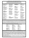
Fig. 23
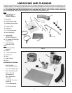
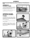
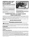
ASSEMBLING DUST INTAKE
HOSES TO BLOWER AND
MOTOR ASSEMBLY
KEEP DUST CAPS INSTALLED AT ALL TIMES OVER
INTAKE PORTS. REMOVE A DUST CAP ONLY WHEN
A FLEXIBLE HOSE IS ATTACHED TO THE INTAKE
PORT.
The dust collector is supplied with a 4" dia. flexible dust
intake hose.
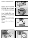
1. To assemble the intake hose (A) Fig. 23, to the blower
assembly, pull the dust cap (B) from the dust intake port
(C) and slide the dust cap collar (D) farther onto the dust
intake port (C) as shown. IMPORTANT: DO NOT RE-
MOVE THE INTAKE CAP FROM THE INTAKE PORT.
2. Place hose clamp (E) Fig. 23, on one end of flexible
hose (A) and assemble the hose to dust intake port (C).
Tighten hose clamp (E).
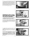
Should you wish to operate your dust collector with a
second intake hose, contact your local Delta Distributor to
purchase the hose and install as in STEPS 1 and 2 above.
Whenever one of the dust intake ports is not in use,
always be sure the dust cap is properly installed in the
intake port for operator safety.
ALWAYS DISCONNECT DUST COLLECTOR FROM
THE POWER SOURCE BEFORE CONNECTING OR
DISCONNECTING INTAKE HOSE.
CONNECTING TOOL TO POWER SOURCE
POWER CONNECTIONS
A separate electrical circuit should be used for your tools. This circuit should not be less than #12 wire and should be
protected with a 20 Amp time lag fuse. Have a qualified electrician repair or replace damaged or worn cord
immediately. Before connecting the motor to the power line, make certain the switch is in the “OFF” position and be
sure that the electric current is of the same characteristics as stamped on the motor nameplate. All line connections
should make good contact. Running on low voltage will damage the motor.
WARNING: DO NOT EXPOSE THE DUST COLLECTOR TO RAIN OR OPERATE THE MACHINE IN DAMP
LOCATIONS.
MOTOR SPECIFICATIONS
Your tool is wired for 120 volt, 60 HZ alternating current. Before connecting the tool to the power source, make sure
the switch is in the “OFF” position.
GROUNDING INSTRUCTIONS
WARNING: THIS TOOL MUST BE GROUNDED WHILE IN USE TO PROTECT THE OPERATOR FROM
ELECTRIC SHOCK.
This tool must be grounded. If it should malfunction or break down, grounding provides a path of least resistance for
electric current to reduce the risk of electric shock. This tool is equipped with a cord having an equipment-grounding
conductor and grounding plug. The plug must be inserted into an appropriate outlet that is properly installed and
grounded in accordance with all local codes and ordinances.
WARNING: Improper connection of the equipment-grounding conductor can result in a risk of electric
shock. Check with a qualified electrician or service person if you are in doubt as to whether the outlet is properly
grounded. Do not modify the plug provided with the dust collector. If it will not fit the outlet, have a proper outlet
installed by a qualified electrician.
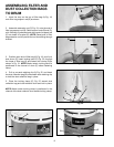
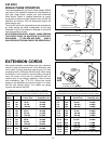
120 VOLT,
SINGLE PHASE OPERATION
This tool must be grounded while in use to protect the operator from electric shock. The motor recommended for use
with your dust collector is shipped wired for 120 Volt, Single Phase, and is equipped with an approved 3-conductor
cord and 3-prong grounding type plug to fit the proper grounding type receptacle, as shown in Fig. 24. The green
conductor in the cord is the grounding wire. Never connect the green wire to a live terminal.
A temporary adapter, shown in Fig. 25, is available for connecting 3-prong grounding type plugs to 2-prong receptacles
if a properly grounded outlet is not available. The temporary adapter should be used only until a properly grounded
outlet can be installed by a qualified electrician. THIS ADAPTER IS NOT APPLICABLE IN CANADA. The green-
colored rigid ear, lug, etc., extending from the adapter, is the grounding means and must be connected to a permanent
ground such as to a properly grounded outlet box, as shown in Fig. 25. Whenever the adapter is used, it must be held
in place with a metal screw.
A
B
E
D
C