


10
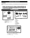
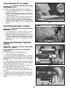
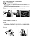
ATTACHING MACHINE TO STAND
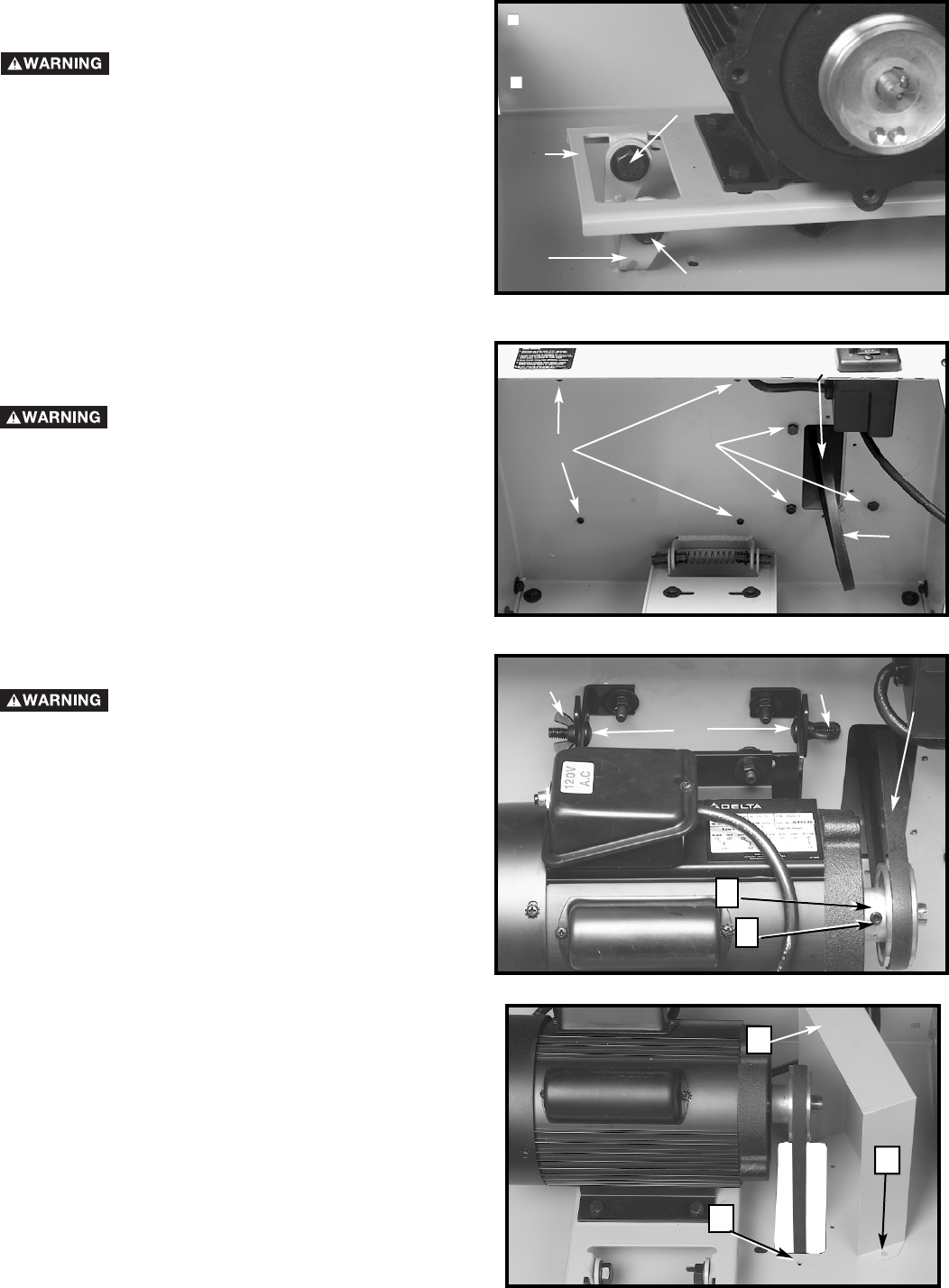
DISCONNECT MACHINE FROM POWER
SOURCE.
1. Pull the belt (A) Fig. 8 down through the smaller
rectangular hole (B) in the top shelf of the stand.
2. Fasten the machine to the top shelf with four 5/16" x
1/2" bolts and lockwashers (C) Fig. 8 (three of which
are shown) and four #10-32 self-tapping screws and
washers (D). (The motor was removed for easier
viewing here.)
10
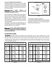
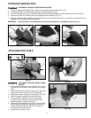
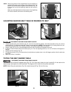
ATTACHING MOTOR TO STAND
DISCONNECT MACHINE FROM POWER
SOURCE.
The motor comes with an attachment bracket installed.
1. Locate the welded bracket (A) Fig. 7 underneath the
top shelf of the stand.
2. Place the motor attachment bracket (B), so that the
holes in the attachment bracket align with the holes in
the welded bracket (A).
3. Insert the hex head bolts - one of which is shown at (C)
- and flat washers, in the holes from the inside out.
4. Using an
11
/16" open end wrench, tighten the locknuts -
one of which is shown at (D) - on the hex head bolts.
Hold the hex head bolts with an
11
/16" socket as you
tighten.
Fig. 8
A
B
C
D
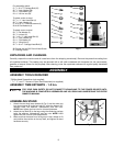
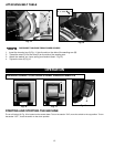
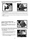
INSTALLING DRIVE BELT AND BELT
GUARD
DISCONNECT MACHINE FROM POWER
SOURCE.
NOTE: MAKE SURE THE BELT IS ON THE SANDER
DRIVE PULLEY.
1. Slip belt (A) Fig. 8A, over motor pulley (B).
2. Allow motor to drop and pull belt tight.
3. Be sure the pulleys are aligned properly. To adjust,
loosen set screw (E) Fig. 8A with a 3/16 hex wrench and
move motor pulley to proper position. Once set, retighten
set screw.
4. Other adjustments are possible. Loosen screws (D)
and (C) Fig 8A and slide sanding unit right or left if needed.
Retighten all hardware before continuing.
5. Insert carriage bolts (C) Fig. 8A from inside out to
attach free end of motor to motor mounts.
6. Place washer and lockwasher on carriage bolts.
7. Thread wing nut (D) onto carriage bolts and tighten
securely.
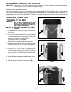
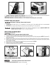
8. Place belt guard (F) Fig. 8B over pulley and belt. Align
the holes in the guard (G) with the holes in the shelf (H).
Fasten the guard to the shelf with four #10-32 machine
screws.
A
B
C
D
D
Fig. 7
Fig. 8A
Fig. 8B
E
B
A
C
D
F
H
G