


1414
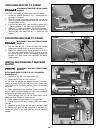
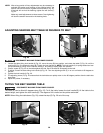
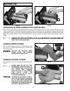
After a long period of time, adjustments may be necessary to
maintain the tension and tracking of the sanding belt. If the
belt will not hold its tension, tighten the set screw (G) Fig. 22.
If the belt will not hold its tracking, tighten the set screw (F)
Fig. 22.
Make only small adjustments to these screws. Over-tightening
will lock the tension lever and/or the tracking knob.
NOTE:
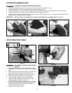
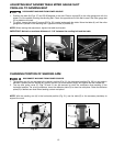
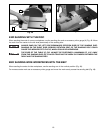
1. Loosen the table tilting lock handle (A) Fig. 23, move the stop (B) into position, and rotate the table (C) Fig. 24 until the
trunnion (D) Fig. 23 contacts the stop (B). Tighten the lock handle (A). NOTE: The lock handle (A) is spring-loaded and can
be repositioned by pulling out the handle, moving it, and letting it spring back into position.
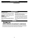
2. Place a square (E) Fig. 24 on the table against the belt. See if the table is 90 degrees to the belt.
3. To adjust, loosen the table tilting lock handle (A) Fig. 23. Turn the adjusting screw (F) in or out until table is 90 degrees to
the belt.
4. Tighten the lock handle (A) Fig. 23.
5. The adjusting screw (F) Fig. 23 ensures that the belt table can rapidly return to the 90 degree position after the table has
been tilted.
6. Adjust the pointer, if necessary.
ADJUSTING SANDING BELT TABLE 90 DEGREES TO BELT
DISCONNECT MACHINE FROM POWER SOURCE.
Fig. 22
Fig. 23
Fig. 24
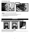
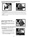
TILTING THE BELT SANDER TABLE
DISCONNECT MACHINE FROM POWER SOURCE.
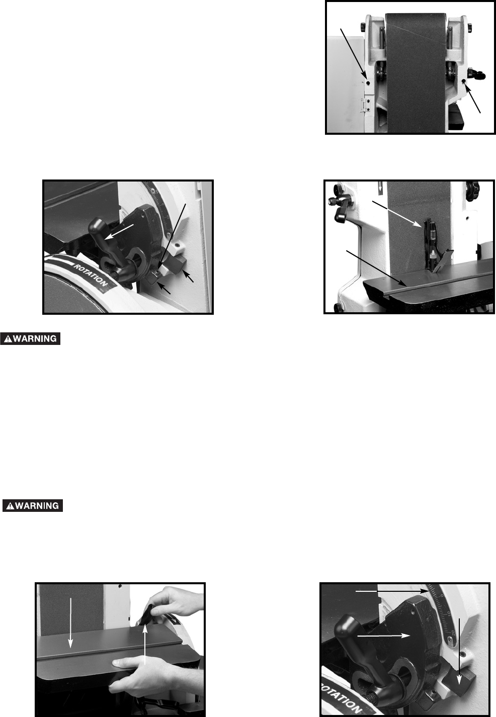
The table (A) can be tilted 45 degrees down (Fig. 25). To tilt the table, loosen the lock handle (B), tilt the table to the
desired angle, and tighten the lock handle (B). The degree of tilt is noted on the pointer and scale.
NOTE: When tilting the table down (Fig. 25), rotate the stop (E) Fig. 26 out of the way.
Fig. 25
Fig. 26
G
F
A
B
C
D
F
E
A
B
C
D
E