


17
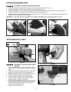
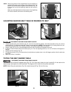
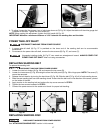
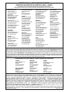
REPLACING SANDING BELT
To replace the sanding belt:
1. Loosen the two lock knobs (A) Fig. 38, and remove the top cover (B).
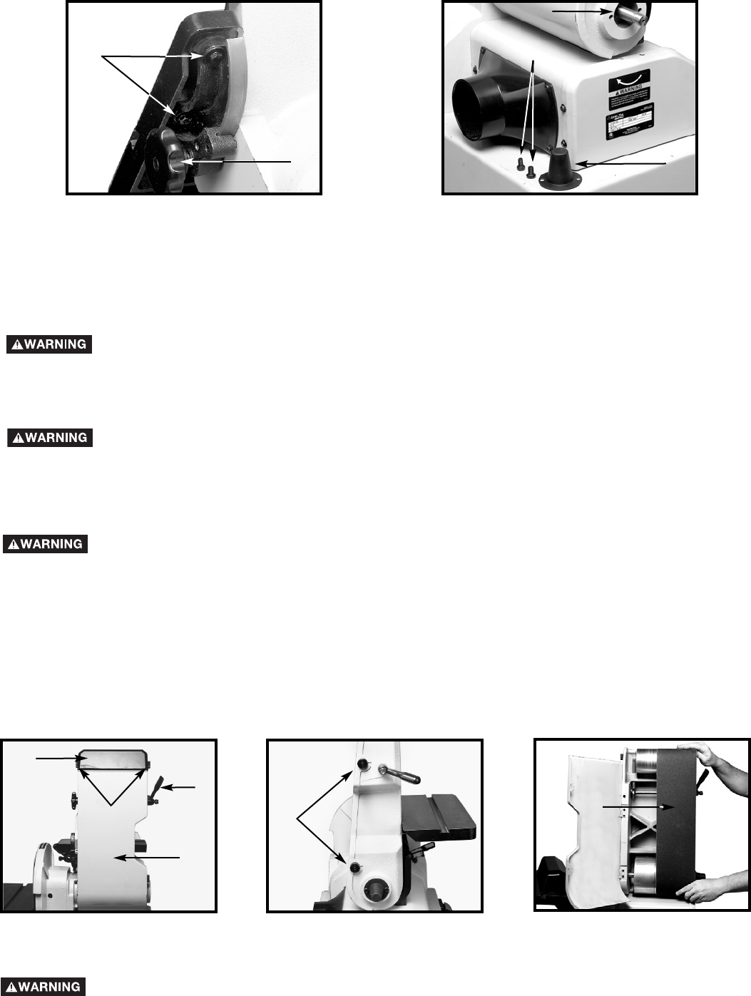
2. Loosen the two screws (C) Fig. 39 enough to allow the back panel (D) Fig. 38 to hinge open. NOTE: The screw (C)
cannot be removed.
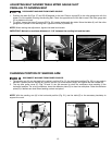
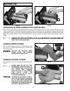
3. Release the belt tension by turning the hand lever (E) Fig. 38. Slide the belt (F) Fig. 40 off of both sanding drums.
4. Slide the new sanding belt over both sanding drums. Ensure that the belt runs in the direction of the arrow, printed
on the inside of the belt.
5. Apply tension to the sanding belt and replace the top cover removed in STEP 2.
6. Tighten the two screws loosened in STEP 3.
7. Connect the power source to the sander and check for proper belt tracking.
Fig. 38
Fig. 39
REPLACING SANDING DISC
See “ATTACHING SANDING DISC” section in this manual.
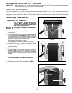
DISCONNECT MACHINE FROM POWER SOURCE
DISCONNECT MACHINE FROM POWER SOURCE.
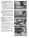
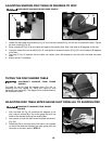
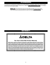
POWER TAKE-OFF SHAFT
1. A power take-off shaft (A) Fig. 37 is provided on the lower end of the sanding belt arm to accommodate
accessories.
2. For access to the power take-off shaft, remove the two screws (B) Fig. 37, and cover (C).
Fig. 37
DISCONNECT MACHINE FROM POWER SOURCE
Unguarded rotating shafts (A) Fig 37 can create an entanglement hazard. ALWAYS COVER THE
POWER TAKE-OFF SHAFT when not using accessories.
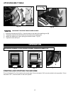
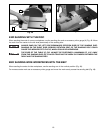
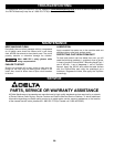
4. To adjust, loosen the four screws, two of which are shown at (D) Fig. 36. Adjust the table until the miter gauge slot
is parallel to the disc. Tighten the four screws (D).
NOTE: When making this adjustment, tighten the lock handle (A) Fig. 36.
IMPORTANT: Maintain a maximum distance of 1/16" between the sanding disc and the table.
Fig. 36
Fig. 40
D
A
A
B
C
A
B
E
C
F
D