


9
Fig. 22
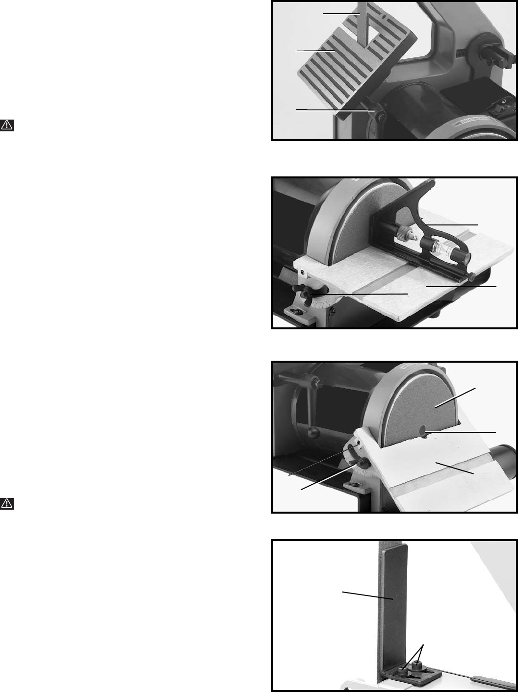
Fig. 21
Fig. 20
Fig. 19
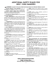
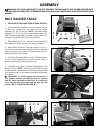
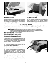
The disc table (C) can be tilted down 45 degrees (Fig.
21), by loosening the two wing nuts (one of which is
shown at (B) Fig. 21). Tilt the table to the desired angle
and tighten the two wing nuts.
NOTE: The power take-off location is shown at (D) Fig.
21, and can be used with the table in the tilted down
position. The accessory flexible shaft can be attached at
this location (leaving the abrasive on the sanding disc)
by cutting a small hole in the center of the abrasive to
provide an entrance for the flexible shaft.
The disc table can be adjusted in or out by loosening the
two set screws (F) Fig. 21 (one of which is shown), and
adjusting table and retightening the two set screws (F).
WARNING: To avoid trapping the workpiece or
your fingers between the table (C) and the
sanding disc (D), adjust the table so that there is a
maximum 1/16" between the work table and the disc
(Fig. 21).
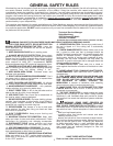
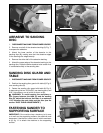
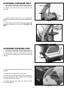
DISC TABLE ADJUSTMENTS
Check the table surface angle by placing a square (A)
Fig. 20 on the table with one end of the square against
the sanding disc. If angle is not 90 degrees, loosen the
two wing nuts (one of which is shown at (B) Fig. 20), and
move the table until the angle between the table and the
disc is 90 degrees. Tighten the two wing nuts.
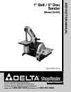
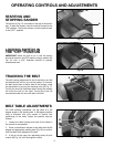
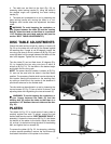
4. The table can be tilted to the front (Fig. 19), by
loosening table locking handle (C), tilting the table to
the desired angle and tightening the table locking
handle (C).
5. The table can be adjusted in or out by loosening the
table locking handle and moving the table in or out.
Retighten lock handle when the adjustment has been
made.
WARNING: To avoid trapping the workpiece or
your fingers between the table (D) and the sanding
belt (E), adjust the table so that there is a maximum
1/16" between the work table and the belt (see the
section “BELT TABLE ADJUSTMENTS”).
C
E
A
B
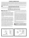
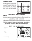
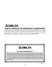
PLATEN
The platen (A) Fig. 22, is constructed of heavy steel to
properly support the work. To adjust, remove the belt
sander table (see the section “BELT SANDER TABLE” in
assembly). Loosen the two screws (B) Fig. 22, that fasten
the bottom of the platen to the frame, adjust the platen
(A), so that it is almost touching the back of the sanding
belt, and tighten the two screws (B).
To remove the platen (A) Fig. 22, for stropping, polishing
or other special operations, remove the two screws (B)
that fasten the bottom of the platen to the frame.
B
C
C
D
D
E
F
A
B