


10
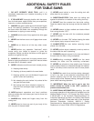
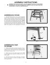
Fig. 7
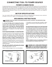
Fig. 8
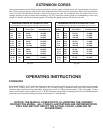
Fig. 9
Fig. 10
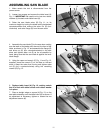
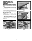
2. Assemble flat washer (not shown), and lock knob (E)
Fig. 8, on end of raising screw shaft.
3. Assemble tilting screw handwheel (F), flat washer
(not shown), and lock knob (G) Fig. 8, to the blade tilting
screw shaft in the same manner, as shown in Fig. 8.
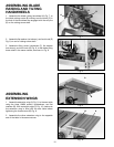
ASSEMBLING BLADE
RAISING AND TILTING
HANDWHEELS
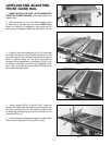
1. Assemble the blade raising handwheel (A) Fig. 7, to
the blade raising screw (B) making sure the slots (C) in
the hub of the handwheel are engaged with the roll pins
(D) on the raising screw shaft.
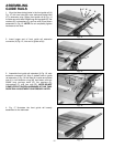
ASSEMBLING
EXTENSION WINGS
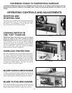
1. Assemble extension wing (A) Fig. 9, to the saw table
using the three 16MM screws, lockwashers, and flat
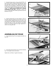
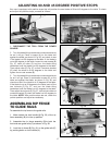
washers (B). With a straight edge (C) Fig. 10, make sure
the extension wing is level with the saw table before
tightening the three screws (B) Fig. 9.
2. Assemble the other extension wing to the opposite
end of the table in the same manner.
A
C
D
B
F
G
E
A
B
B
C
A
D