


18
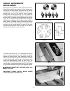
Fig. 41
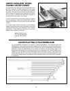
Fig. 42
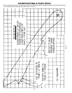
Fig. 43
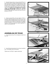
RIP FENCE OPERATION
AND ADJUSTMENTS
IMPORTANT: THE RIP FENCE MUST BE PROPERLY
ALIGNED TO THE MITER GAGE SLOT IN ORDER TO
PREVENT KICKBACK WHEN RIPPING.
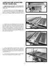
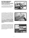
1. To move the fence (A) Fig. 41, along the guide rails,
lift up on the fence locking lever (B), slide the fence to
the desired location on the guide rails and push down on
the locking lever (B) to lock the fence in position.
2. The fence (A) Fig. 41, must be adjusted so it is
parallel to the miter gage slots (C). To check and adjust,
move fence (A) until the bottom edge of the fence is in
line with the edge of one of the miter gage slots as
shown, and push down on the fence locking lever (B).
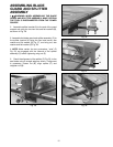
Check to see if the fence (A) is parallel to the edge of the
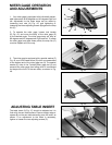
miter gage slot (C) the entire length of the table. If an
adjustment must be made, slightly tighten or loosen one
of the two adjusting screws (D) or (E) Fig. 42. Check
again to see if the edge of the fence is parallel with the
miter gage slot the entire length of the slot. Repeat this
adjustment until you are sure the fence is parallel with
the miter gage slot. IMPORTANT: DO NOT REMOVE
THE RIP FENCE FROM THE GUIDE RAIL TO MAKE
THIS ADJUSTMENT. VERY LITTLE MOVEMENT OF
SCREWS (D) AND (E) FIG. 42, IS NECESSARY TO
ADJUST THE FENCE PARALLEL WITH THE MITER
GAGE SLOT.
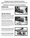
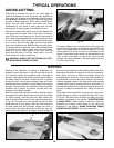
3. The distance the fence is positioned away from the
blade is indicated by the witness line (F) Fig. 43, located
on the cursor (G). If it is necessary to adjust the cursor
(G), make a test cut with the fence locked in position.
Measure the width of the finished cut and adjust the
cursor (G) by loosening the two screws (H), adjusting the
cursor (G) until the witness line (F) is aligned with the
same marking on the scale (K) as the finished cut. Then
tighten the two screws (H).
C
B
A
D
E
H
G
K
F