


English
7
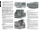
cutting wheel cover. Press the spindle lock button (U)
while tightening the cutting wheel nut.
4. Replace cover and tighten screw (R).
5. Adjust cutting wheel depth (see Cutting Depth
Adjustment).
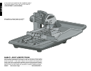
TO ATTACH THE EDGE GUIDE (FIG. 12)
1. Place edge guide (J) on the cutting cart assembly (H).
2. Turn the edge guide lock (W) clockwise to tighten.
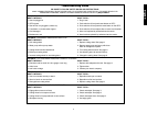
Specifications
Voltage............................120 V
Amps ..............................15A
RPM................................4200
Depth of Cut ..................3-3/4"
Miter Angels....................22.5˚ and 45˚
Cutting Wheel sizes........7", 8", 9" and 10" Continuous
Rim Cutting wheels and 6"
Profile Wheel
OPERATION
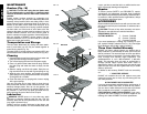
Tool Placement
Place stand (D24001, see Accessories) on a level sur-
face. Place the saw into the stand as shown in Figure 21.
If not using a stand, place saw on a level surface.
Motor
Be sure your power supply agrees with the nameplate
marking. Voltage decrease of more than 10% will cause
loss of power and overheating. All D
EWALT tools are fac-
tory tested; if this tool does not operate, check the power
supply.
• Always plug saw into a GFCI receptacle.
• Always plug extension cord into a GFCI receptacle.
• Use only extension cords that are intended for outdoor
use. These extension cords are identified by a mark-
ing “Acceptable for use with outdoor appliance; store
indoors while not in use.”
• Use only extension cords having an electrical rating
not less than the rating of the product.
• Do not use damaged extension cords. Examine exten-
sion cord before using and replace if damaged.
• Do not abuse extension cords and do not yank on any
cord to disconnect.
• Keep cord away from heat and sharp edges.
• Always disconnect the extension cord from the
receptacle before disconnecting the product from the
extension cord.
On/Off Switch
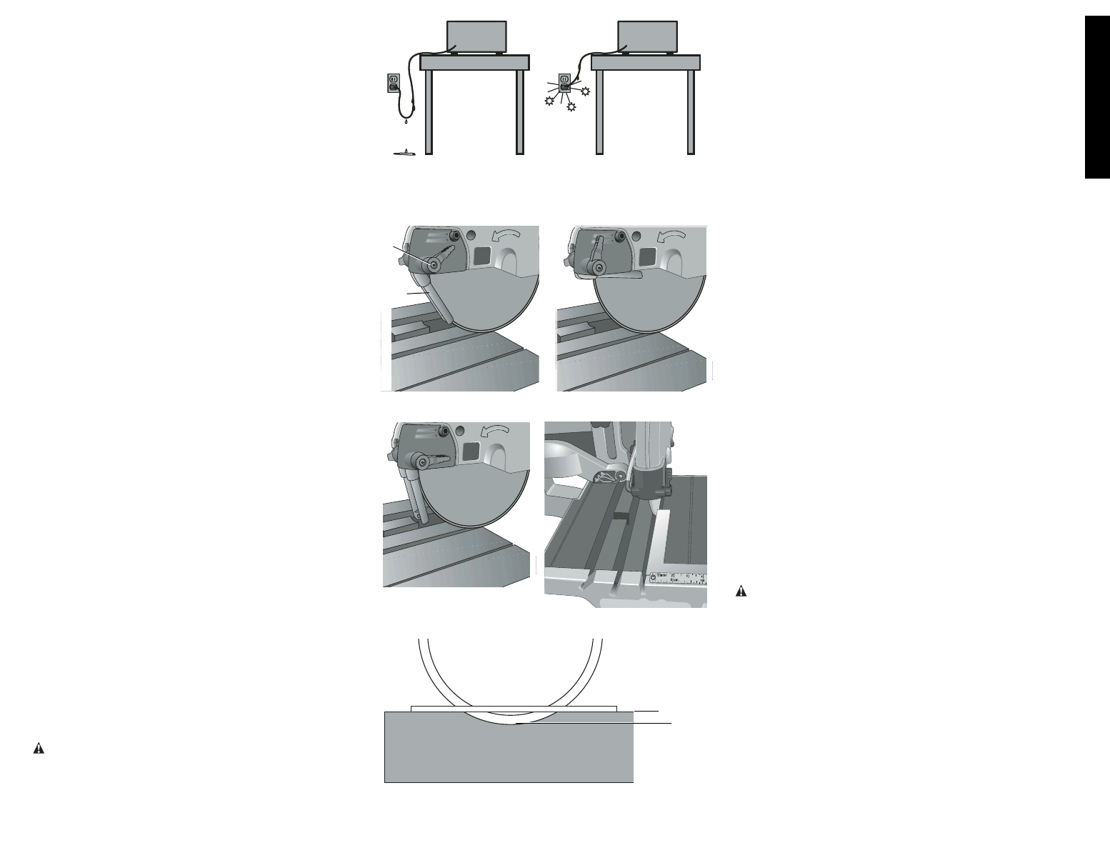
WARNING: To avoid the possibility of the appliance
plug or receptacle getting wet, position the wet tile saw to
one side of a wall mounted receptacle to prevent water
from dipping onto the receptacle or plug. The user should
arrange a “drip loop” in the cord connecting the saw to a
receptacle (Fig. 6). The “drip loop” is that part of the cord
below the level of the receptacle, or the connector if an
extension cord is used, to prevent water traveling along
the cord and coming in contact with the receptacle.
To turn the wet tile cutter on, lift up the on/off switch (A).
The wet tile saw locks on automatically. To turn the tool off,
push the on/off switch down. A hole is provided under the
switch for insertion of a padlock to deter unauthorized use.
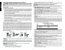
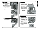
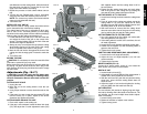
Water Nozzles
Water nozzles (M) are adjustable to provide maximum
water for cutting and maximum capacity with the minimum
amount of overspray and mist. The adjusting lever (V)
allows easy adjustment of nozzles to desired position.
1. Optimum position for minimum overspray (Fig. 7).
2. Water nozzles (M) can be fully retracted to allow for
maximum capacity (Fig. 8).
3. “Off Cutting Wheel” position to eliminate water over-
spray between cuts and for blade change (Fig. 9).
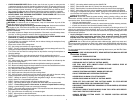
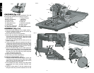
Cutting Wheel Alignment
TO CHECK ALIGNMENT (FIG. 10)
1. Place a 90˚ framing square on the cutting cart fence
(X).
2. Push the cutting cart along the cutting wheel to deter-
mine if the gap along the framing square is consistent
along the length of the stroke.
3. If the gap is not consistent, see the Adjustments sec-
tion of this manual.
Cutting Wheel Depth (Fig. 11)
The outer rim of the cutting wheel should always be at
least 3/16" (5mm) below the cart surface. Push cart entire-
ly through the cutting wheel before cutting to be sure that
the cutting wheel depth is properly adjusted to avoid cut-
ting the cart.
If the cutting wheel height is not set, see the Adjustments
section of this manual. Failure to adjust properly could
cause damage or injury.
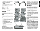
Making a Cut (Fig. 12)
CAUTION: Turn off and unplug the tool before mak-
ing any adjustments or removing or installing attach-
ments or accessories. Be sure the switch is in the OFF
position.
Before turning the saw on, verify the proper alignment of
the cutting cart and cutting wheel. Always center the cutting
wheel in one of the cutting cart grooves (Y) before cutting
(0˚, 22.5˚ or 45˚). If the cutting wheel is not centered in the
cart groove, please see the Adjustments section of this
manual.
1. Fill a 5 gallon bucket with water. Submerge the water
pump into the bucket.
2. Place the tile to be cut onto the cutting cart and secure
the edge guide (J) with the edge guide lock (W).
Always keep hands away from the cutting wheel.
FIG. 6
FIG. 8
FIG. 7
FIG. 9
V
M
FIG. 11
3/16" (5 MM)
FIG. 10