


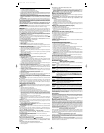
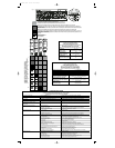
Adjusting Depth (Figures 3, 4)
The depth that the fastener is driven can be adjusted using the depth adjustment next to the
trigger of the tool.
WARNING: To reduce risk of serious injury from accidental actuation when attempt-
ing to adjust depth, ALWAYS:
• Lock OFF trigger.
• Disconnect air supply.
• Avoid contact with trigger during adjustments.
1. To drive the nail shallower, rotate the depth setting wheel (K) to the right (Fig. 3).
2. To drive a nail deeper, rotate the depth setting wheel (K) to the left (Fig. 4).
Shingle Gauge Adjustment (Fig. 6)
1. Lock off trigger.
2. Disconnect air supply.
3. Loosen the screw (L) with the Allen key provided. Move the gauge (M) up or down to attain
desired position.
4. Tighten the screw.
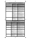
Clearing a Jammed Nail (Fig. 5)
If a nail becomes jammed in the nosepiece, keep the tool pointed away from you and follow
these instructions to clear:
1. Lock OFF trigger.
2. Disconnect the air supply from the tool.
3. Open the canister door (G).
4. Open the nail guide door (H).
5. Remove the jammed nail.
6. Correct any deformation that may have occurred to the nail coil.
NOTE: Should nails continue to jam frequently in nosepiece, have tool serviced by an
authorized D
EWALT service center.
Cold Weather Operation
When operating tools at temperatures below freezing:
1. Make sure compressor tanks have been properly drained prior to use.
2. Keep tool as warm as possible prior to use.
3. Make certain all fasteners have been removed from canister.
4. Put 5 to 10 drops of D
EWALT Pneumatic Tool Oil in the air inlet.
5. Lower air pressure to 80 psi or less.
6. Reconnect air and and load nails into canister.
7. Actuate the tool 5 or 6 times into scrap lumber to lubricate O-rings.
8. Turn pressure up to operating level (not to exceed 120 psi) and use tool as normal.
9. Re-lubricate at least once daily.
10. Always drain the compressor tanks at least once a day.
Hot Weather Operation
Tool should operate normally. However, keep tool out of direct sunlight as excessive heat can
deteriorate bumpers, O-rings and other rubber parts resulting in increased maintenance.
MAINTENANCE (Figures 7, 8, 9)
Daily Maintenance Chart
ACTION Lubricate tool with 5-7 drops of DEWALT Pneumatic Tool Oil.
WHY Prevents failure of O-rings.
HOW Insert drops into air fitting on end cap of tool.
ACTION Drain compressor tanks and hoses daily.
WHY Prevents accumulation of moisture in compressor and nailer.
HOW Open petcocks or other drain valves on compressor tanks. Allow any accumulated water
to drain from hoses.
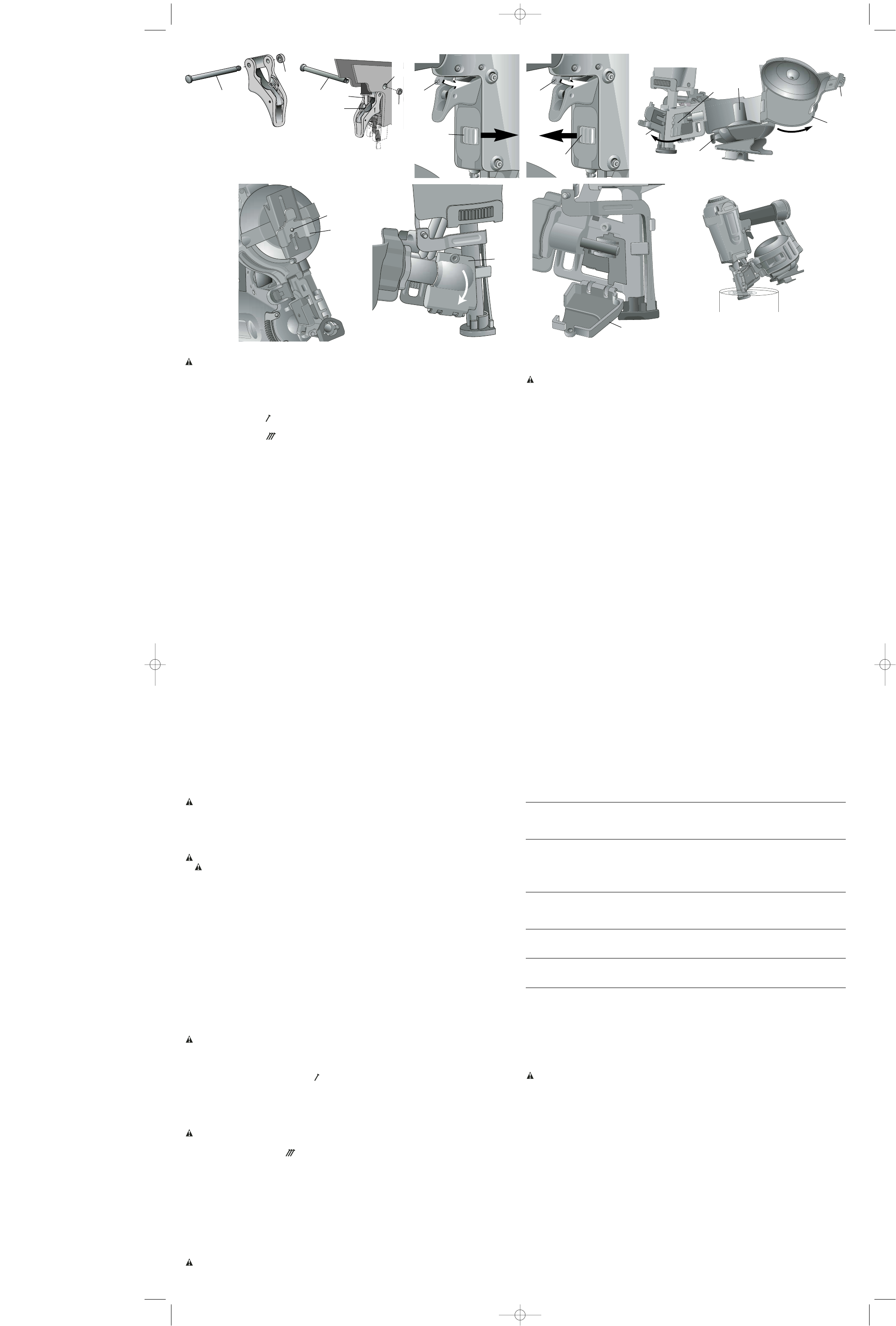
ACTION Clean contact trip.
WHY Permits smooth operation of contact trip.
HOW Dip the front end of the tool into solvent allowing the dust and dirt to dissolve (Fig. 9). Dry
off nailer before use. NOTE: Only use kerosene, #2 fuel oil, or diesel fuel as a solvent.
NEVER use gasoline, this will damage the O-rings. DO NOT dip the tool beyond the feed
piston.
ACTION Clean canister.
WHY Permits smooth operation of tool and allows nails to consistently move into the feeder sec-
tion of the tool.
HOW Blow clean with compressor air.
ACTION Clean feed piston area.
WHY Permits smooth operation of feed pawl.
HOW Open feed piston cover (N) as shown in Figures 7 and 8. Blow clean with compressor air.
ACTION Before each use, check to insure all screws, nuts and fasteners are tight and undamaged.
WHY Prevents jams, leaks and premature failure of tool parts.
HOW Tighten loose screws or other fasteners using the appropriate allen wrench or screwdriver.
Repairs
To assure product SAFETY and RELIABILITY, repairs, maintenance and adjustment should
be performed by authorized service centers or other qualified service personnel, always using
identical replacement parts. Refer to the Troubleshooting Guide at the end of this section.
Accessories
Recommended accessories for use with your tool are available for purchase from your local
dealer or authorized service center. If you need assistance in locating any accessory for your
tool, contact: D
EWALT Industrial Tool Co., 701 East Joppa Road, Baltimore, MD 21286 (1-800-
4-DEWALT).
WARNING: Only use accessories recommended by D
E
WALT. The use of any other acces-
sory not recommended for use with this tool could be hazardous.
Three Year Limited Warranty
DEWALT will repair, without charge, any defects due to faulty materials or workmanship for
three years from the date of purchase. This warranty does not cover part failure due to normal
wear or tool abuse. For further detail of warranty coverage and warranty repair information,
visit www.dewalt.com or call 1-800-4-D
EWALT (1-800-433-9258). This warranty does not apply
to accessories or damage caused where repairs have been made or attempted by others. This
warranty gives you specific legal rights and you may have other rights which vary in certain
states or provinces.
In addition to the warranty, D
EWALT tools are covered by our:
1 YEAR FREE SERVICE
D
EWALT will maintain the tool and replace worn parts caused by normal use, for free, any time
during the first year after purchase. Nailer wear items, such as O-rings and driver blades, are
not covered.
90 DAY MONEY BACK GUARANTEE
If you are not completely satisfied with the performance of your D
EWALT Power Tool, Laser,
or Nailer for any reason, you can return it within 90 days from the date of purchase with a
receipt for a full refund – no questions asked.
FREE WARNING LABEL REPLACEMENT: If your warning labels (Fig. 10) become illegible
or are missing, call 1-800-4-D
EWALT for a free replacement.
ASSEMBLY
CAUTION: Lock off trigger, disconnect air line from tool and remove fasteners from canis-
ter before making adjustments.
Trigger
In accordance with the ANSI Standard SNT-101-2002, the DEWALT Nailers are assembled with
a bump action trigger. However, a sequential action trigger kit is included and attached to the
tool. For a replacement trigger contact your authorized service center or call 1-800-4-D
EWALT.
The gray trigger with imprinted on the side, (Cat.# D510022 kit) is the single sequential
action trigger and causes the tool to operate in this mode.
The black trigger with imprinted on the side, (Cat.# D510020 kit) is the bump action trig-
ger and permits the tool to be actuated in this manner.
For defining the use of the sequential action trigger and bump action trigger, see the
Actuating Tool section of this manual.
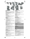
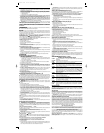
TRIGGER REMOVAL (FIG. 1)
1. Lock off trigger.
2. Remove air from the tool.
3. Remove rubber grommet (A) from end of dowel pin (B).
4. Remove dowel pin.
5. Remove trigger assembly from trigger cavity under the handle of the tool housing.
TRIGGER INSTALLATION (FIG. 2)
1. Select either the sequential or bump trigger to be installed on the tool. Both triggers are
included in the tool packaging.
2. Insert the trigger subassembly into trigger cavity.
3. Ensure that trigger spring (C) is placed around the trigger valve stem (D).
4. Align the holes of the trigger with the housing holes (E), then insert the dowel pin (B)
through the entire assembly as shown.
5. Push the rubber grommet (A) onto the end of the dowel pin as shown.
OPERATION
Preparing the Tool
1.
Read Safety Instruction section of this manual.
2. LUBRICATE TOOL
a. Use D
EWALT Pneumatic Tool Oil or a non-detergent S.A.E. 20 weight oil. DO NOT use
detergent oil or additives as they will damage O-rings and rubber parts.
b. Use a Filter and Regulator when possible.
c. Add 5 to 7 drops of oil in the air fitting a least twice a day.
3. Wear eye and ear protection.
4. Ensure canister is empty of all fasteners.
5. Check for smooth and proper operation of contact trip. Do not use tool if assembly is not
functioning properly. NEVER tamper with the contact trip. NEVER use a tool that has the
contact trip restrained in the actuated position.
6. CHECK AIR SUPPLY: Ensure air pressure does not exceed recommended operating
limits; 70 to 120 psi, (4.9 to 8.3 bar, 5 to 8.5 kg/cm
2
).
7. Keep tool pointed away from yourself and others.
8. Lock off trigger.
9. Connect air hose.
10. Check for audible leaks around valves and gaskets. Never use a tool that leaks or has
damaged parts.
Using the Lock-off (Figures 3, 4)
WARNING: Always wear eye and ear protection when operating tool.
Each DEWALT nailer is equipped with a trigger lock-off switch (P) which when rotated to the
right, prevents the tool from actuating. When the switch is centered, the tool will be fully oper-
ational. The trigger should always be locked off whenever any adjustments are made or when
tool is not in use.
Loading the Tool (Fig. 5)
CAUTION: Keep tool pointed in a safe direction when loading nails.
CAUTION: Never load nails with the contact trip or trigger activated.
1. Lock OFF trigger.
2. Disconnect the air supply from the tool.
3. Pull the canister latch (R) to open the canister door (G).
4. Place your finger under the nail guide door (H) and pull to open the door.
5. Rotate the nail platform adjustment lever (F) to properly accommodate the nail length being
used. There are three different positions. The lowest position is used for 1-1/2" to 1-3/4"
(38 - 45 mm) nails, the center position is used for 1" to 1-1/2" (25 - 38 mm) nails and the
highest position is used for 3/4" to 7/8" (19 - 25 mm) nails.
6. Place the nail coil on spindle (I) in canister.
7. Uncoil enough nails (approximately 3") to reach the nose of the tool.
8. Insert the first nail into the nose and the second nail between the two rails of the feed
pawl (J).
NOTE: Be careful not to deform the coil of nails during the loading process. Otherwise, the
nail guide door will not close and the nails might not feed consistently.
9. Close the nail guide door (H) completely.
10. Close the canister door (G) completely by engaging the canister latch (R) with your fingers
and locking the canister closed.
Actuating Tool
WARNING: Always wear eye and ear protection when operating tool.
The tool can be actuated using one of two modes: single sequential action trigger mode and
bump action trigger mode. The trigger installed on the tool as described in the Trigger section
of this manual determines the mode of operation.
SEQUENTIAL ACTION TRIGGER - (GRAY)
The sequential action trigger’s intended use is for intermittent nailing where very careful and
accurate placement is desired.
To operate the nailer in sequential action mode:
1. Depress the contact trip firmly against the work surface.
2. Depress the trigger.
CAUTION: A nail will fire each time the trigger is depressed as long as the contact trip
remains depressed.
BUMP ACTION TRIGGER - (BLACK)
The bump action trigger’s intended use is for rapid nailing on flat, stationary surfaces.
Using the bump action trigger, two methods are available: place actuation and bump
actuation.
To operate the tool using the PLACE ACTUATION method:
1. Depress the contact trip against the work surface.
2. Depress the trigger.
To operate the tool using the BUMP ACTUATION method:
1. Depress the trigger.
2. Push the contact trip against the work surface. As long as the trigger is depressed, the tool
will fire a nail every time the contact trip is depressed. This allows the user to drive multi-
ple nails in sequence.
CAUTION: Do not keep trigger depressed when tool is not in use. Keep the lock-off switch
rotated to the right (OFF) when the tool is not in use.
P
P
FIG. 9
FIG. 3
FIG. 4
FIG. 6
FIG. 8
FIG. 5
A
B
E
D
B
C
A
FIG. 1
FIG. 2
FIG. 7
N
N
K
K
L
M
G
F
H
I
J
R
614989-00, D51321 3/19/04 5:45 PM Page 3