


10
English
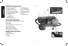
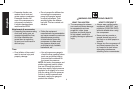
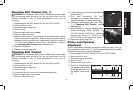
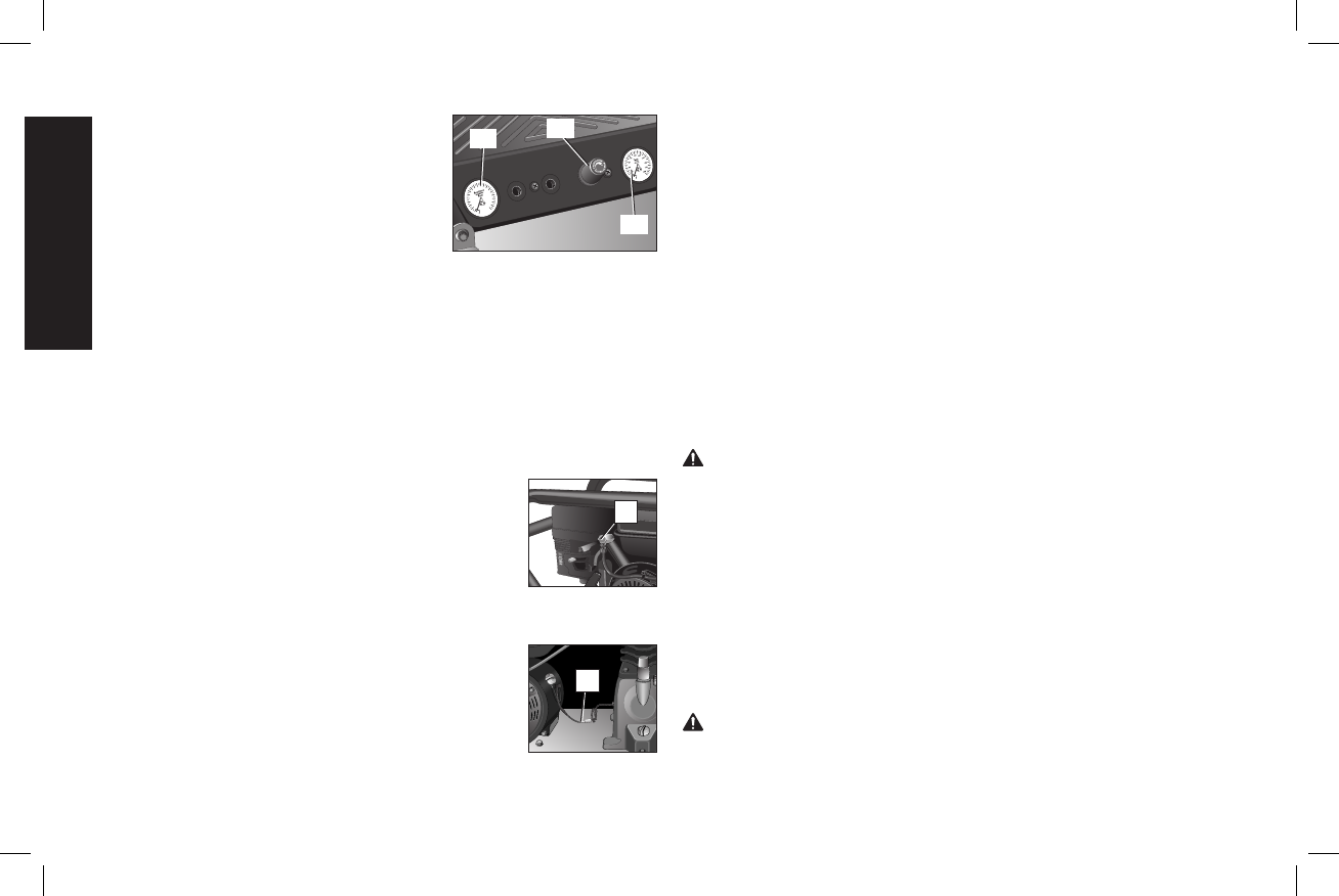
REGULATED PRESSURE GAUGE
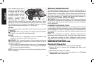
The regulated pressure gauge (E) indicates
2
00
180
160
14
0
120
10
0
8
0
60
40
2
0
E
F
D
the air pressure available at the outlet side
of the regulator. This pressure is controlled
by the regulator and is always less or equal
to the air tank pressure.
REGULATOR
The regulator knob (F) controls the air pressure coming from the air
tank.
Adjusting Regulator
1. Pull regulator knob (F) out.
2. Turn knob clockwise to increase regulated pressure and
counterclockwise to decrease regulated pressure.
3. When desired pressure is shown on the regulated pressure
gauge push knob in to lock.
THROTTLE CONTROL
When maxi mum air tank pres sure is reached and
K
the unloader valve vents air, it activates the throttle
control (K) on the engine. This gas saving feature
holds the engine at a factory-set idling speed until
air pressure in the air tank drops to reset pressure.
The unloader valve then reactivates the throttle
control and accelerates the engine to full throttle.
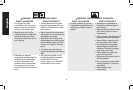
LOW OIL SHUT DOWN SENSORS
The air compressor engine and pump are equipped
O
with low oil shutdown sensors (O). These are
safety devices designed to protect your engine and
pump from damage in the event the oil level in the
crankcase is below minimum.
If the oil in the pump or engine gets low while the air compressor is
running it will automatically shut down the engine and will not restart
until oil is added to the engine or pump. If the oil is low before start-
up, the engine will not start until oil is added.
NOTE: The low oil shutdown sensors are very sensitive. You must
fill the engine and pump to the full mark on the dipstick to inactivate
this safety device.
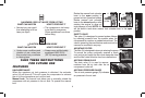
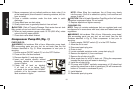
INSTALLATION
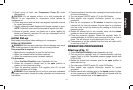
Assembly (Fig. 1)
HANDLE
Assembly handle (P) to handle bracket (Q) using hardware supplied.
The nuts supplied will not spin onto bolts, after two turns a wrench,
ratchet, or air tool needs to be used to tighten securely.
INSTALLING HOSES
WARNING: Risk of unsafe operation. Firmly grasp hose in hand
when installing or disconnecting to prevent hose whip.
1. Ensure regulated pressure gauge reads 0 PSI (0 kPa).
2. Apply sealant tape to hose threads.
3. Assemble hose(s) to air outlet(s) (G). IMPORTANT: Do not
assemble splitters directly to the air outlet(s) (G).
NOTE: Assembling quick connect bodies to air outlets (G) and quick
connect plugs to hose ends make connecting and disconnecting
hoses simple and easy. Quick connect bodies and plugs are
available for purchase from your local dealer or authorized service
center.
DISCONNECTING HOSES
WARNING: Risk of unsafe operation. Firmly grasp hose in hand
when installing or disconnecting to prevent hose whip.
1. Ensure regulated pressure gauge reads 0 PSI (0 kPa).