


English
10
WARNING: A workpiece that is clamped, balanced
and secure before a cut may become unbalanced after
a cut is completed. An unbalanced load may tip the
saw or anything the saw is attached to, such as a table
or workbench. When making a cut that may become
unbalanced, properly support the workpiece and ensure
the saw is firmly bolted to a stable surface. Personal injury
may occur.
WARNING: The clamp foot must remain clamped above
the base of the saw whenever the clamp is used. Always
clamp the workpiece to the base of the saw–not to any
other part of the work area. Ensure the clamp foot is not
clamped on the edge of the base of the saw.
CAUTION: Always use a work clamp to maintain
control and reduce the risk of workpiece damage and
personal injury.
If you cannot secure the workpiece on the table and
against the fence by hand, (irregular shape, etc.) or your
hand would be less than 6" (152 mm) from the blade, a
clamp or other fixture should be used.
For best results use the DW7082 clamp made for use
with your saw. It is available through your local retailer or
D
EWALT service center at extra cost.
Other aids such as spring clamps, bar clamps or C-clamps
may be appropriate for certain sizes and shapes of
material. Use care in selecting and placing these clamps.
Take time to make a dry run before making the cut. The
left fence will slide from side to side to aid in clamping.
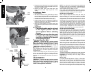
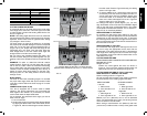
TO INSTALL CLAMP (SOLD SEPARATELY)
1. Insert it into the hole behind the fence. The clamp
should be facing toward the back of the miter saw.
The groove on the clamp rod should be fully inserted
into the base. Ensure this groove is fully inserted into
the base of the miter saw. If the groove is visible, the
clamp will not be secure.
2. Rotate the clamp 180º toward the front of the miter
saw.
3. Loosen the knob to adjust the clamp up or down,
then use the fine adjust knob to firmly clamp the
workpiece.
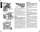
NOTE: Place the clamp on the opposite side of the
base when beveling. ALWAYS MAKE DRY RUNS
(UNPOWERED) BEFORE FINISH CUTS TO CHECK
THE PATH OF THE BLADE. ENSURE THE CLAMP
DOES NOT INTERFERE WITH THE ACTION OF THE
SAW OR GUARDS.
WARNING: A workpiece that is clamped, balanced
and secure before a cut may become unbalanced after
a cut is completed. An unbalanced load may tip the
saw or anything the saw is attached to, such as a table
or workbench. When making a cut that may become
unbalanced, properly support the workpiece and ensure
the saw is firmly bolted to a stable surface.
WARNING: The clamp foot must remain clamped
above the base of the saw whenever the clamp is used.
Always clamp the workpiece to the base of the saw–not to
any other part of the work area. Ensure the clamp foot is
not clamped on the edge of the base of the saw.
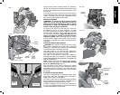
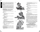
SUPPORT FOR LONG PIECES
WARNING: To reduce the risk of serious personal
injury, turn off the tool and disconnect it from the
power source before attempting to move it, change
accessories or make any adjustments accept as
written in laser adjustment instructions.
ALWAYS SUPPORT LONG PIECES.
Never use another person as a substitute for a table
extension; as additional support for a workpiece that is
longer or wider than the basic miter saw table or to help
feed, support or pull the workpiece.
For best results, use the DW7080 extension work support
to extend the table width of your saw. Available from your
dealer at extra cost.
Support long workpieces using any convenient means
such as sawhorses or similar devices to keep the ends
from dropping.
CUTTING PICTURE FRAMES, SHADOW BOXES AND
OTHER FOUR-SIDED PROJECTS
To best understand how to make the items listed here,
we suggest that you try a few simple projects using scrap
wood until you develop a “FEEL” for your saw.
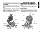
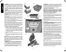
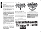
Your saw is the perfect tool for mitering corners like the
one shown in Figure 17. Sketch A in Figure 17 shows
a joint made by using the bevel adjustment to bevel the
edges of the two boards at 45° each to produce a 90°
corner. For this joint the miter arm was locked in the zero
position and the bevel adjustment was locked at 45°. The
wood was positioned with the broad flat side against the
table and the narrow edge against the fence. The cut could
also be made by mitering right and left with the broad
surface against the fence.
CUTTING TRIM MOLDING AND OTHER FRAMES
Sketch B in Figure 17 shows a joint made by setting the
miter arm at 45° to miter the two boards to form a 90°
corner. To make this type of joint, set the bevel adjustment
to zero and the miter arm to 45°. Once again, position the
wood with the broad flat side on the table and the narrow
edge against the fence.
The two sketches in Figure 17 are for four sided objects
only.
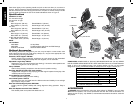
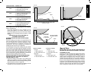
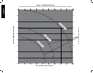
As the number of sides changes, so do the miter and
bevel angles. The chart below gives the proper angles for
a variety of shapes. The chart assumes that all sides are
of equal length. For a shape that is not shown in the chart,
use the following formula. 180° divided by the number of
sides equals the miter or bevel angle.
FIG. 18
FIG. 19
FIG. 17
A.
B.
ANGLE “A”
FIG. 21
FIG. 20
MITER
SCALE