


Dust Bag: DW7053 (Included with some models)
Equipped with a zipper for easy emptying, the dust bag will capture the majority of the
sawdust produced (not shown).
Crown Molding Fence: DW7084
Used for precision cutting of crown molding.
Kerf Plate Blank: DW7055
Used to limit back side tear out of material or as a replacement kerf plate (not shown).
Miter Saw LED Worklight System: DWS7085
Lighting used for greater visibility and cutting alignment during operation. Easy to install.
SAW BLADES: ALWAYS USE 12" (305 mm) SAW BLADES WITH 1" (25.4 mm) ARBOR
HOLES. SPEED RATING MUST BE AT LEAST 4800 RPM. Never use a smaller diameter
blade. It will not be guarded properly. Use crosscut blades only! Do not use blades designed
for ripping, combination blades or blades with hook angles in excess of 7º.
BLADE DESCRIPTIONS
APPLICATION DIAMETER TEETH
Construction Saw Blades (thin kerf with anti-stick rim)
General Purpose 12" (305 mm) 40
Fine Crosscuts 12" (305 mm) 60
Woodworking Saw Blades (provide smooth, clean cuts)
Fine crosscuts 12" (305 mm) 80
Non-ferrous metals 12" (305 mm) 96
NOTE: For cutting non-ferrous metals, use only saw blades with
TCG teeth designed for this purpose.
Unpacking Your Saw
Check the contents of your miter saw carton to make sure that you have received all parts. In
addition to this instruction manual, the carton should contain:
1. One No. DW716 miter saw.
2. One D
EWALT 12" (305 mm) dia. saw blade
3. One blade wrench in wrench pocket shown in Figure 2.
4. One DW7053 dustbag (some models).
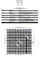
Specifications
CAPACITY OF CUT
50º miter left and right
48º bevel left and right
0º miter
Max. Height 3.6" (91.5 mm) Result Width 7.2" (183 mm)
Max. Width 7.9:" (200.7 mm) Result Height 2.9" (73.7mm)
45º miter
Max. Height 3.6" (91.5 mm) Result Width 4.9" (125 mm)
Max. Width 5.5” (140 mm) Result Height 2.9" (73.7 mm)
45º bevel - Left
Max. Height 2.3" (58.4 mm) Result Width 7.4" (188 mm)
Max. Width 7.9" (200.7 mm) Result Height 1.9" (48.3 mm)
45º bevel - Right
Max. Width 7.9" (200.7 mm) Result Height 1.1" (28 mm)
Max. Height 1.6" (40.6 mm) Result Width 7.1" (180.3 mm)
Your saw is capable of cutting baseboard moldings 0.9" (22.9 mm) thick by 6" (152 mm) tall on a
45º right or left miter.
NOTE: Your saw is capable of cutting the following once a special set-up procedure is followed
(see Special Cuts).
0º miter height 1.5" (38.1 mm)
width 10" (255 mm)
45º miter height 1.5" (38.1 mm)
width 7.5" (190.5 mm)
DRIVE
120 Volt Motor
1675 Watts (max in) 15 Amp Motor
3600 RPM Cut Helical Gears
Multi-V Belt Roller Bearings
Automatic Electric Brake Carbide Blade
Familiarization
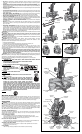
Your miter saw is fully assembled in the car ton. Open the box and lift the saw out by the con-
venient carry ing handle, as shown in Figure 1A. Place the saw on a smooth, flat surface such as
a workbench or strong table. Examine Figure 2 to become familiar with the saw and its various
parts. The section on adjus tments will refer to these terms and you must know what and where
the parts are.
CAUTION: Pinch Hazard. To reduce the risk of injury, keep thumb underneath the handle
when pulling the handle down. The lower guard will move up as the handle is pulled down which
could cause pinching. The handle is placed close to the guard for special cuts.
Press down lightly on the operating handle and pull out the lock down pin, as shown in Figure 2.
Gently release the downward pressure and hold the arm allowing it to rise to its full height. Use the
lock down pin when carrying the saw from one place to another. Always use the carrying handle
to transport the saw or the hand indentations shown in Figure 2 and 4.
Bench Mounting
Holes are provided in all four feet to facilitate bench mounting, as shown in Figure 2. (Two
different sized holes are provided to accommodate different sizes of screws. Use either hole,
it is not necessary to use both.) Always mount your saw firmly to a stable surface to prevent
movement. To enhance the tool’s portability, it can be mounted to a piece of 1/2" (12.7 mm) or
thicker plywood which can then be clamped to your work support or moved to other job sites
and reclamped.
NOTE: If you elect to mount your saw to a piece of plywood, make sure that the mounting screws
don’t protrude from the bottom of the wood. The plywood must sit flush on the work support.
When clamping the saw to any work surface, clamp only on the clamping bosses where the
mounting screw holes are located. Clamping at any other point will surely interfere with the
proper operation of the saw.
CAUTION: To prevent binding and inaccuracy, be sure the mounting surface is not warped or
otherwise uneven. If the saw rocks on the surface place a thin piece of material under one saw
foot until the saw sits firmly on the mounting surface.
IMPORTANT SAFETY INSTRUCTIONS
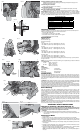
Changing or Installing a New Saw Blade (Fig. 3)
WARNING: To reduce the risk of serious personal injury, turn off the tool and disconnect
it from the power source before attempting to move it, change accessories or make any
adjustments accept as written in laser adjustment instructions.
CAUTION:
• Never depress the spindle lock button while the blade is under power or coasting.
• Do not cut ferrous metal (containing iron or steel) or masonry or fiber cement product with
this miter saw.
Removing the Blade
1. Unplug the saw.
2. Raise the arm to the upper position and raise the lower guard (A) as far as possible.
3. Loosen, but do not remove guard bracket screw (B) until the bracket can be raised far
enough to access the blade screw. Lower guard will remain raised due to the position of the
guard bracket screw.
4. Depress the spindle lock button (C) while carefully rotating the saw blade by hand until the
lock engages.
5. Keeping the button depressed, use the other hand and the wrench provided (D) to loosen
the blade screw. (Turn clockwise, left-hand threads.)
6. Remove the blade screw (E), outer blade clamp (F), and blade (G). The 1" (25.4mm) blade
adapter (H), if used, and the inner blade clamp (I), may be left on the spindle.
NOTE: For blades with a blade hole of 5/8" (15.88 mm), the 1" (25.4 mm) blade adapter is
not used.
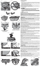
FIG. 6
MITER
SCALE
POINTER
POINTER
ADJUSTMENT
SCREW
FIG. 8
L
S
R
R
P
U
O
N
FIG. 11
FIG. 4
FIG. 5
J
K
FIG. 7
T
L
FIG. 9
SCREWS
(two each
side)
FIG. 10
V
FIG. 3
A
B
D
E
F
G
H
FIG. 3B
I
C
FIG. 3A
M