


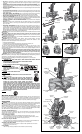

Installing a Blade
1. Unplug the saw.
2. With the arm raised, the lower guard held open and the guard bracket raised, place the
blade on the spindle, onto the blade adapter [if using a blade with a 1" (25.4 mm) diameter
blade hole] and against the inner blade clamp with the teeth at the bottom of the blade
pointing toward the back of the saw.
3. Assemble the outer blade clamp onto the spindle.
4. Install the blade screw and, engaging the spindle lock, tighten the screw firmly with wrench
provided. (Turn counterclockwise, left-hand threads.)
NOTE: When using blades with a 5/8" (15.88 mm) diameter blade hole, the blade adapter will not
be used and should be stored in a safe place for future use.
5. Return the guard bracket to its original position and firmly tighten the guard bracket screw
to hold bracket in place.
WARNING:
• The guard bracket must be returned to its original position
and the screw tightened before activating the saw.
• Failure to do so may allow the guard to contact the spinning
saw blade resulting in damage to the saw and severe personal
injury.
Transporting the Saw
WARNING: To reduce the risk of serious personal injury, turn off the tool and disconnect
it from the power source before attempting to move it, change accessories or make any
adjustments accept as written in laser adjustment instructions.
WARNING: To reduce the risk of serious personal injury, ALWAYS lock the miter lock
handle, bevel lock handle, lock down pin and fence adjustment knobs before transporting saw.
In order to conveniently carry the miter saw from place to place, a carrying handle has been
included on the top of the saw arm and hand indentations in the base, as shown in Figures 2, 4.
Adjustments
WARNING: To reduce the risk of serious personal injury, turn off the tool and disconnect
it from the power source before attempting to move it, change accessories or make any
adjustments accept as written in laser adjustment instructions.
NOTE: Your miter saw is fully and accurately adjusted at the factory at the time of manufacture.
If readjustment due to shipping and handling or any other reason is required, follow the steps
below to adjust your saw.
Once made, these adjustments should remain accurate. Take a little time now to follow these
directions carefully to maintain the accuracy of which your saw is capable.
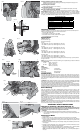
MITER SCALE ADJUSTMENT (FIG. 5)
Place a square against the saw’s fence and blade. (Do not touch the tips of the blade teeth with
the square. To do so will cause an inaccurate measure ment.) Unlock miter lock lever (J) and
swing the miter arm until the miter latch locks it at the 0 miter position. Do not lock miter lock
lever (J). If the saw blade is not exactly perpendicular to the fence, loosen the three screws that
hold the miter scale to the base and move the scale left or right until the blade is perpendicular
to the fence, as measured with the square. Retighten the three screws. Pay no attention to the
reading of the miter pointer at this time.
MITER POINTER ADJUSTMENT (FIG. 5, 6)
To unlock, lift the miter lock lever (J) up and squeeze the miter latch (K) to move the miter arm
to the zero position. With the miter lock lever unlocked allow the miter latch to snap into place
as you rotate the miter arm to zero. Observe the pointer and miter scale through the viewing
opening shown in Figure 6. If the pointer does not indicate exactly zero, loosen the screw
holding the pointer in place, reposition the pointer and tighten the screw.
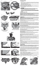
BEVEL SQUARE TO TABLE (FIG. 7)
To align the blade square to the rotary table, lock the arm in the down position. Place a square
against the blade taking care to not have the square on top of a tooth. Loosen the bevel lock
knob (L) and ensure the arm is firmly against the 0º bevel stop. Move the 0º bevel stop adjusting
screw (T) as necessary so that the blade is at 0º bevel to the table.
BEVEL POINTER (FIG. 7)
If the bevel pointer (M) does not indicate zero, loosen the screw that holds it in place and
move the pointer as necessary. Do not remove the steel plate in front of the bevel pointer. This
plate prevents wood resin from accumulating on the bevel scale during use.
ADJUSTING THE BEVEL STOP TO 45º LEFT OR RIGHT (FIG. 8)
NOTE: Adjust the 45º bevel angles only after performing the 0º bevel angle and pointer
adjustment. Ensure the 45º bevel override levers (N) are pushed inward to obtain an accurate
adjustment.
To adjust the right 45º bevel angle, loosen the bevel lock knob (L) and pull the bevel stop override
knob (S) to override the 0º bevel stop. When the saw is fully to the right, if the pointer does not
indicate exactly 45º, turn the right bevel stop screw (O) until the pointer indicates 45º.
To adjust the left 45º bevel stop, first loosen the bevel lock knob (L) and tilt the head to the left.
If the pointer does not indicate exactly 45º, turn the left bevel stop screw until the pointer reads
45º.
ADJUSTING THE BEVEL STOP TO 33.85º (FIG. 8)
NOTE: Adjust the 33.85º bevel angles only after performing the 0º bevel angle and pointer
adjustment.
To set the 33.85º bevel angle, flip out the stop pawls (P). Loosen the bevel lock knob (L) and tilt
the head to the left. If the pointer does not indicate exactly 33.85º, turn the screw contacting the
pawl until the pointer reads 33.85º.
To adjust the right 33.85º bevel angle, flip out the stop pawl. Loosen the bevel lock knob (L) and
pull the bevel stop override button (S) to override the 0º bevel stop. When the saw is fully to the
right, if the pointer does not indicate exactly 33.85º, turn the screw contacting the pawl until the
pointer indicates 33.85º.
FENCE ADJUSTMENT
WARNING: To reduce the risk of serious personal injury, turn off the tool and
disconnect it from the power source before attempting to move it, change accessories
or make any adjustments accept as written in laser adjustment instructions.
In order that the saw can bevel to a full 48° left or right, the fences can be adjusted to provide
clearance. To adjust a fence, loosen the plastic knob (Figure 8, R), and slide the fence outward.
Make a dry run with the saw turned off and check for clearance. Adjust the fence to be as close
to the blade as practical to provide max imum workpiece support, without interfering with arm
up and down movement. Tighten knob securely. When the bevel operations are complete, don’t
forget to relocate the fence.
NOTE: The guide groove of the fences can become clogged with sawdust. If you notice that it is
becoming clogged, use a stick or some low pressure air to clear the guide groove.
AUTOMATIC ELECTRIC BRAKE
Your saw is equipped with an automatic electric blade brake which stops the saw blade within
5 seconds of trigger release. This is not adjustable.
On occasion, there may be a delay after trigger release to brake engagement. On rare occasions,
the brake may not engage at all and the blade will coast to a stop.
If a delay or “skipping” occurs, turn the saw on and off 4 or 5 times. If the condition persists, have
the tool serviced by an authorized D
EWALT service center.
Always be sure the blade has stopped before removing it from the kerf. The brake is not a
substitute for guards. Ensure your own safety by giving the saw your complete attention.
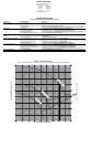
FIG. V1
MITER
ANGLE
CENTER MARK ON VERNIER SCALE
ALIGNS WITH DESIRED WHOLE
ANGLE ON MITER SCALE
(24° RIGHT MITER)
KERF PLATE
FIG. V2
1/4° VERNIER MARK ALIGNS WITH
CLOSEST WHOLE DEGREE MARK ON
MITER SCALE (24-1/4° RIGHT MITER)
FIG. 18
BLADE
FENCE
RIGHT
FIG. 18A
BLADE
FENCE
WRONG
FIG. 19
RIGHT
FIG. 19A
WRONG
ALWAYS ADJUST FENCE
PROPERLY BEFORE USE
FIG. 20
FIG. 14
FIG. 13
A
B
FIG. 15
ANGLE “A”
FIG. 16
FIG. 12
PROPER CUT
FIG. 12A
IMPROPER CUT
FIG. 17
FENCE
TABLE
CROWN MOLDING FLAT ON TABLE AND
AGAINST FENCE
CROWN MOLDING BETWEEN FENCE
AND TABLE
TABLE
FENCE
BOTTOM SIDE
OF MOLDING
TOP SIDE
OF MOLDING
FIG. 17A
DW7084
CROWN
MOLDING
FENCE
SET
SCREW
FIG. 21
SCREWS