


VERNIER SCALE
Your saw is equipped with a vernier scale for added precision. The vernier scale allows you to
accurately set miter angles to the nearest 1/4°. To use the vernier scale follow the steps listed
below.
(As an example, let’s assume that the angle you want to miter is 24-1/4° right).
1. Turn off miter saw.
2. Set the miter angle to the nearest whole degree desired by aligning the center mark in the
vernier scale, shown in Figure V1, with the whole degree number etched in the miter scale.
Examine Figure V2 closely; the setting shown is 24° right miter.
3. To set the additional 1/4°, squeeze the miter arm lock and carefully move the arm to the
RIGHT until the 1/4° vernier mark aligns with the CLOSEST degree mark on the miter scale.
In our example, the closest degree mark on the miter scale happens to be 25°. Figure V2
shows a setting of 24-1/4° right miter.
For settings that require partial degrees (1/4, 1/2, 3/4°) align the desired vernier mark with the
CLOSEST degree mark on the miter scale, as described below (The plastic vernier plate is
inscribed with marks for 1/4, 1/2, 3/4 and 1°. Only the 1/2° and the 1° are numerically labeled.)
WHEN MITERING TO THE RIGHT
To increase the miter angle when mitering to the right, move the arm to align the appropriate
vernier mark with the closest mark on the miter scale to the right. To decrease the miter angle
when mitering to the right, move the arm to align the appropriate vernier mark with the closest
mark on the miter scale to the left.
WHEN MITERING TO THE LEFT
To increase the miter angle when mitering to the left, move the arm to align the appropriate
vernier mark with the closest mark on the miter scale to the left. To decrease the miter angle
when mitering to the left, move the arm to align the appropriate vernier mark with the closest
mark on the miter scale to the right.
CUTTING BASE MOLDING
ALWAYS MAKE A DRY RUN WITHOUT POWER BEFORE MAKING ANY CUTS.
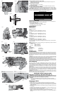
Straight 90° cuts:
Position the wood against the fence and hold it in place as shown in Figure 16. Turn on the
saw, allow the blade to reach full speed and lower the arm smoothly through the cut.
CUTTING BASE MOLDING UP TO 6" (152 MM) VERTICALLY AGAINST THE FENCE
Position material as shown in Figure 16.
All cuts made with the back of the molding against the fence and bottom of the molding against
the base.
INSIDE CORNER: OUTSIDE CORNER:
Left side Left side
1. Miter left 45 1. Miter right at 45°
2. Save left side of cut 2. Save left side of cut
Right side Right side
1. Miter Right 45° 1. Miter left at 45°
2. Save right side of cut 2. Save right side of cut
Material up to 6" (152 mm) can be cut as described above.
CUTTING CROWN MOLDING
Your miter saw is better suited to the task of cutting crown molding than any tool made. In order
to fit properly, crown molding must be compound mitered with extreme accuracy.
The two flat surfaces on a given piece of crown molding are at angles that, when added together,
equal exactly 90°. Most, but not all, crown molding has a top rear angle (the section that fits
flat against the ceiling) of 52° and a bottom rear angle (the part that fits flat against the wall)
of 38°.
Your miter saw has special pre-set miter latch points at 31.62° left and right for cutting crown
molding at the proper angle and bevel stop pawls at 33.85º left and right. There is also a mark
on the bevel scale at 33.85°.
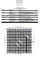
The chart below gives the proper settings for cutting crown molding. (The numbers for the
miter and bevel settings are very precise and are not easy to accurately set on your saw.)
Since most rooms do not have angles of precisely 90°, you will have to fine tune your
settings anyway.
PRETESTING WITH SCRAP MATERIAL IS EXTREMELY IMPORTANT!
INSTRUCTIONS FOR CUTTING CROWN MOLDING LAYING FLAT AND USING THE
COMPOUND FEATURES:
1. Molding laying with broad back surface down flat on saw table (Figure 17).
2. The settings below are for All Standard (U.S.) crown molding with 52° and 38° angles.
BEVEL SETTING TYPE OF CUT
LEFT SIDE, INSIDE CORNER:
33.85° Left 1. Top of molding against fence
2. Miter table set right 31.62°
3. Save left end of cut
RIGHT SIDE, INSIDE CORNER:
33.85° Right 1. Top of molding against fence.
2. Miter table set at left 31.62°
3. Save right end of cut
LEFT SIDE, OUTSIDE CORNER:
33.85° Right 1. Top of molding against fence.
2. Miter table set at left 31.62°
3. Save left end of cut
RIGHT SIDE, OUTSIDE CORNER:
33.85° Left 1. Top of molding against fence
2. Miter table set right 31.62°
3. Save right end of cut
When setting bevel and miter angles for all compound miters, remember that:
The angles presented for crown moldings are very precise and difficult to set exactly. Since
they can easily shift slightly and very few rooms have exactly square corners, all settings
should be tested on scrap molding.
PRETESTING WITH SCRAP MATERIAL IS EXTREMELY IMPORTANT!
ALTERNATIVE METHOD FOR CUTTING CROWN MOLDING
Place the molding on the table at an angle between the fence and the saw table, as shown
in Figure 17A. Use of the crown molding fence accessory (DW7084) is highly recommended
because of its degree of accuracy and convenience. The crown molding fence accessory is
available for purchase from your local dealer.
The advantage to cutting crown molding using this method is that no bevel cut is required.
Minute changes in the miter angle can be made without affecting the bevel angle. This way,
when corners other than 90° are encountered, the saw can be quickly and easily adjusted for
them. Use the crown molding fence accessory to maintain the angle at which the molding will
be on the wall.
INSTRUCTIONS FOR CUTTING CROWN MOLDING ANGLED BETWEEN THE FENCE
AND BASE OF THE SAW FOR ALL CUTS:
1. Angle the molding so the bottom of the molding (part which goes against the wall when
installed) is against the fence and the top of the molding is resting on the base of the saw, as
shown in Figure 17A.
2. The angled “flats” on the back of the molding must rest squarely on the fence and base of the
saw.
INSIDE CORNER: OUTSIDE CORNER:
Left side Left side
1. Miter right 45 1. Miter left at 45°
2. Save right side of cut 2. Save right side of cut
Right side Right side
1. Miter left 45° 1. Miter right at 45°
2. Save left side of cut 2. Save left side of cut
Special Cuts
NEVER MAKE ANY CUT UNLESS THE MATERIAL IS SECURED ON THE TABLE
AND AGAINST THE FENCE.
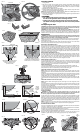
ALUMINUM CUTTING
ALWAYS USE THE APPROPRIATE SAW BLADE MADE ESPECIALLY FOR CUTTING
ALUMINUM. These are available at your local D
EWALT retailer or DEWALT service center.
Certain workpieces, due to their size, shape or surface finish, may require the use of a clamp
or fixture to prevent movement during the cut. Position the material so that you will be cutting
the thinnest cross section, as shown in Figure 18. Figure 18A illustrates the wrong way to cut
these extrusions. Use a stick wax cutting lubricant when cutting aluminum. Apply the stick wax
directly to the saw blade before cutting. Never apply stick wax to a moving blade.
The wax, available at most hardware stores and industrial mill supply houses, provides proper
lubrication and keeps chips from adhering to the blade.
Be sure to properly secure workpiece.
Refer to Saw Blades under Optional Accessories for correct saw blade.
BOWED MATERIAL
When cutting bowed material always position it as shown in Figure 19 and never like that
shown in Figure 19A. Positioning the material incorrectly will cause it to pinch the blade near the
completion of the cut.
CUTTING PLASTIC PIPE OR OTHER ROUND MATERIAL
Plastic pipe can be easily cut with your saw. It should be cut just like wood and CLAMPED OR
HELD FIRMLY TO THE FENCE TO KEEP IT FROM ROLLING. This is extremely important
when making angle cuts.
CUTTING LARGE MATERIAL
Occasionally you will encounter a piece of wood a little too large to fit beneath the blade guard.
If this occurs, simply place your right thumb on the upper side of the guard and roll the guard
up just enough to clear the workpiece, as shown in Figure 20. Avoid doing this as much as
possible, but if need be, the saw will operate properly and make the bigger cut. NEVER TIE,
TAPE, OR OTHERWISE HOLD THE GUARD OPEN WHEN OPERATING THIS SAW.
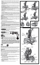
SPECIAL SET-UP FOR WIDE CROSSCUTS
Your saw can cut very wide [up to 10" (406 mm)] workpieces when a special set up is used. To
set the saw up for these workpieces, follow these steps:
1. Remove both left and right sliding fences from the saw and set aside. To remove them,
unscrew the fence knobs several turns and slide each fence outward. Adjust and lock the
miter control so that it is at 0° miter.
2. Make a platform using a piece of 1.5 inch (38 mm) thick particleboard or similar flat strong
1.5" (38 mm) thick wood to the dimensions: 10" x 24" (254 x 610 mm). The platform must be
flat otherwise the material could move during cutting and cause injury.
3. Mount the 10" x 24" (254 x 610 mm) platform to the saw using 4 three-inch (76 mm) long
wood screws through the holes in the base fence (Fig. 9). Four screws must be used to
properly secure the material. When the special set up is used, the platform will be cut into
two pieces. Ensure the screws are tightened properly otherwise material could loosen and
cause injury. Ensure the platform is firmly flat on the table, against the fence, and centered
evenly from left to right.
WARNING: Ensure the saw is mounted firmly to a stable flat surface. Failure to do so could
cause the saw to be unstable and fall causing personal injury.
4. Place the workpiece to be cut on top of the platform mounted to the table. Ensure the
workpiece is firmly against the backfence (Fig. 9).
5. Secure the material before cutting. Cut slowly through the material. Failure to clamp securely
or cut slowly could result in the material coming loose and causing injury.
After several cuts are made at various miter angles other than 0º, the platform may weaken
and not properly support the work. Install a new, unused platform to the saw after presetting the
desired miter angle.
CAUTION: Continued use of a platform with several kerfs may cause loss of material control
and possible injury.
Removing and Replacing Belt
The belt is designed to last the life of the tool. However, abuse of the tool could cause the belt
to fail.
If the blade does not turn when the motor is running, the belt has failed. To inspect or replace the
belt, remove the belt cover screws. Remove the belt cover. Inspect the ribs of the belt for wear or
failure. Check belt tension by squeezing the belt as shown in Figure 21. The belt halves should
almost touch when squeezing firmly with the thumb and index finger.
To adjust the tension, loosen, but do not remove, the four Phillips head screws shown. Then
rotate the set screw on the top of the motor plate casting until the proper tension is achieved.
Tighten the four screws securely and replace the belt cover.
NOTE: Over tightening the belt will cause premature motor failure.
MAINTENANCE
DO NOT use lubricants or cleaners (particularly spray or aerosol) in the vicinity of the plastic
guard. The polycarbonate material used in the guard is subject to attack by certain chemicals.
1. All bearings are sealed. They are lubricated for life and need no further maintenance.
2. Periodically clean all dust and wood chips from around AND UNDER the base and the
rotary table. Even though slots are provided to allow debris to pass through, some dust will
accumulate.
3. The brushes are designed to give you several years of use. If they ever need replacement
follow the instructions or return the tool to the nearest service center for repair. Service
center locations are packed with your tool.
Service Infor mation
Please have the following information available for all service calls:
Model Number _____________________ Serial Number __________________________
Date and Place of Purchase ____________________________________________________
Repairs
To assure product SAFETY and RELIABILITY, repairs, maintenance and adjustment (including
brush inspection and replacement) should be performed by authorized service centers or other
qualified service organizations, always using identical replacement parts.
Three Year Limited Warranty
DEWALT will repair, without charge, any defects due to faulty materials or workmanship for
three years from the date of purchase. This warranty does not cover part failure due to normal
wear or tool abuse. For further detail of warranty coverage and warranty repair information, visit
www.dewalt.com or call 1-800-4-D
EWALT (1-800-433-9258). This warranty does not apply to
accessories or damage caused where repairs have been made or attempted by others. This
warranty gives you specific legal rights and you may have other rights which vary in certain
states or provinces.
In addition to the warranty, D
EWALT tools are covered by our:
1 YEAR FREE SERVICE
D
EWALT will maintain the tool and replace worn parts caused by normal use, for free, any time
during the first year after purchase.
90 DAY MONEY BACK GUARANTEE
If you are not completely satisfied with the performance of your D
EWALT Power Tool, Laser, or
Nailer for any reason, you can return it within 90 days from the date of purchase with a receipt
for a full refund – no questions asked.
LATIN AMERICA: This warranty does not apply to products sold in Latin America. For products
sold in Latin America, see country specific warranty information contained either in the
packaging, call the local company or see website for warranty information.
FREE WARNING LABEL REPLACEMENT: If your warning labels become illegible or are
missing, call 1-800-4-D
EWALT (1-800-433-9258) for a free replacement.