


GUARD ACTUATION AND VISIBILITY
CAUTION: Pinch Hazard. To reduce the risk of injury, keep thumb underneath the handle
when pulling the handle down. The lower guard will move up as the handle is pulled down which
could cause pinching.
The blade guard on your saw has been designed to automatically raise when the arm is brought
down and to lower over the blade when the arm is raised.
The guard can be raised by hand when installing or removing saw blades or for inspection of the
saw. NEVER RAISE THE BLADE GUARD MANUALLY UN LESS THE SAW IS TURNED OFF.
NOTE: Certain special cuts of large material will require that you manually raise the guard.
Refer to Cutting Large Material under Special Cuts.
The front section of the guard is louvered for visibility while cutting. Although the louvers dramati-
cally reduce flying debris, they are openings in the guard and safety glasses should be worn at
all times when viewing through the louvers.
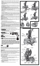
MITER LOCK ADJUSTMENT (FIG. 11)
The miter lock rod should be adjusted if the table of the saw can be moved when the miter
lock handle is locked down. To adjust, put the miter lock handle in the up position. Using a
slotted screwdriver, adjust the lock rod in 1/8 clockwise turn increments to increase the lock
force. To ensure the miter lock is functioning properly, re-lock miter lock handle to a non-detent
miter angle.
Brushes
WARNING: To reduce the risk of serious personal injury, turn off the tool and disconnect
it from the power source before attempting to move it, change accessories or make any
adjustments accept as written in laser adjustment instructions.
Inspect carbon brushes regularly by unplugging tool, removing the motor end cap (Fig. 2), lift
the brush spring and withdraw the brush assembly. Keep brushes clean and sliding freely in
their guides. Always replace a used brush in the same orientation in the holder as it was prior
to its removal. Carbon brushes have varying symbols stamped into their sides, and if the brush
is worn down to approximately 1/2" (12.7 mm), the spring will no longer exert pressure and they
must be replaced. Use only identical D
EWALT brushes. Use of the correct grade of brush is
essential for proper operation of electric brake. New brush assemblies are available at D
EWALT
service centers. The tool should be allowed to “run in” (run at no load) for 10 minutes before
use to seat new brushes. The electric brake may be erratic in operation until the brushes are
properly seated (worn in). Always replace the brush inspection cap after inspection or servicing
the brushes.
While “running in” DO NOT TIE, TAPE, OR OTHER WISE LOCK THE TRIGGER SWITCH ON.
HOLD BY HAND ONLY.
Controls
Your compound miter saw has several main controls, which will be discussed briefly here. For
more information on these controls, see the respective sections later in the manual.
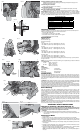
MITER CONTROL (FIG. 5)
The miter lock/adjustment lever and trigger allows you to miter your saw 50º left and right. To
miter the saw, unlock miter lock lever (J) by pulling upward, squeeze the detent trigger (K) and
set the miter angle desired on the miter scale. Lock miter lock handle by pressing downward.
Override the detent trigger by rotating knob (Fig. 10, V).
TRIGGER SWITCH (FIG. 2)
The trigger switch turns your saw on and off. A hole is provided in the trigger for insertion of a
padlock to secure the saw.
BEVEL LOCK (FIG. 8)
The bevel lock knob (L) allows you to bevel the saw 48º left or right. To loosen the handle and
adjust the bevel setting, turn the handle counter clock wise, the saw head bevels easily to the left
or to the right once the 0º bevel override knob (S) is pulled. To tighten, turn the handle clockwise.
Bevel degree markings are on the bottom front of the saw arm (Fig. 7, M).
0º BEVEL OVERRIDE (FIG. 8)
The bevel stop override (S) allows you to bevel the saw to the right past the 0º mark.
The saw will automatically stop at 0º when brought up from the left. To move past 0º to the right,
pull the bevel stop knob. The stop knob can be locked out by pulling the knob out and rotating
it 180º.
45º BEVEL STOP OVERRIDES (FIG. 8)
The bevel stop overrides (N) are held secure with their attachment screw to prevent inadvertent
movement. Use the bit on the blade wrench to loosen the attachment screw. This allows the
slides, to be pulled outward and the saw head to pivot past the 45º mark. Be sure to retighten
the attachment screw when finished.
33.85º BEVEL STOPS (FIG. 8)
The two pawls (P) are used to stop the saw head bevel setting at 33.85º. This setting is used
primarily for cutting crown moldings laid flat on the table.
HEAD DOWNLOCK PIN (FIG. 8)
To lock the saw head in the down position, push the head down, push the pin (U) in and release
the saw head. This will hold the saw head safely down for moving the saw from place to place.
To release, press the saw head down and pull the pin out.
OPERATION
WARNING: To reduce the risk of serious personal injury, turn off the tool and disconnect
it from the power source before attempting to move it, change accessories or make any
adjustments accept as written in laser adjustment instructions.
WARNING: Always use eye protection. All users and bystanders must wear eye protection
that conforms to ANSI Z87.1 (CAN/CSA Z94.3).
Plug the saw into any household 60 Hz power source. Refer to the nameplate for voltage. Be
sure the cord will not interfere with your work.
SWITCH
To turn the saw on, depress the trigger switch. To turn the tool off, release the switch. Allow the
blade to spin up to full operating rpm before making the cut. Release the trigger switch and allow
the brake to stop the blade before raising the saw head. There is no provision for locking the
switch on, but a hole is provided in the trigger for insertion of a padlock to lock the saw off.
CUTTING WITH YOUR SAW
NOTE: Although this saw will cut wood and many non-ferrous materials, we will limit our
discussion to the cutting of wood only. The same guidelines apply to the other materials. DO
NOT CUT FERROUS (IRON AND STEEL) MATERIALS OR MASONRY WITH THIS SAW. Do
not use any abrasive blades.
CROSSCUTS
Cutting of multiple pieces is not recommended but can be done safely by ensuring that each
piece is held firmly against the table and fence. A crosscut is made by cutting wood across the
grain at any angle. A straight crosscut is made with the miter arm at the zero degree position.
Set the miter arm at zero, hold the wood on the table and firmly against the fence. Turn on the
saw by squeezing the trigger.
CAUTION: Always use a work clamp to maintain control and reduce the risk of workpiece
damage and personal injury.
When the saw comes up to speed (about 1 second) lower the arm smoothly and slowly to cut
through the wood. Let the blade come to a full stop before raising arm.
Miter crosscuts are made with the miter arm at some angle other than zero. This angle is often 45°
for making corners, but can be set anywhere from zero to 50° left or right. After selecting the desired
miter angle, be sure to lock miter lock lever. Make the cut as described above.
To cut through an existing pencil line on a piece of wood, match the angle as close as possible.
Cut the wood a little too long and measure from the pencil line to the cut edge to determine
which direction to adjust the miter angle and recut. This will take some practice, but it is a
commonly used technique.
BEVEL CUTS
A bevel cut is a crosscut made with the saw blade at a bevel to the wood. In order to set the
bevel, loosen the bevel clamp knob and move the saw to the left as desired. (It is necessary
to move the fence to allow clearance). Once the desired bevel angle has been set, tighten the
bevel clamp knob firmly.
Bevel angles can be set from 48° right to 48° left and can be cut with the miter arm set between
zero and 50° right or left. At some extreme angles, the right or left side fence might have to be
removed. To remove the left or right fence, unscrew the knobs several turns and slide the fence
out.
QUALITY OF CUT
The smoothness of any cut depends on a number of variables. Things like material being cut, blade
type, blade sharpness and rate of cut all contribute to the quality of the cut.
When smoothest cuts are desired for molding and other precision work, a sharp (60 tooth
carbide) blade and a slower, even cutting rate will produce the desired results.
Ensure that material does not creep while cutting, clamp it securely in place. Always let the blade
come to a full stop before raising arm.
If small fibers of wood still split out at the rear of the workpiece, stick a piece of masking tape
on the wood where the cut will be made. Saw through the tape and carefully remove tape when
finished.
For varied cutting applications, refer to the list of recommended saw blades for your saw and
select the one that best fits your needs. Refer to Saw Blades under Optional Accessories.
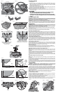
BODY AND HAND POSITION (FIG. 12)
Proper positioning of your body and hands when operating the miter saw will make cutting
easier, more accurate and safer. Never place hands near cutting area. Place hands no closer
than 6" (152 mm) from the blade. Hold the workpiece tightly to the table and the fence when
cutting. Keep hands in position until the trigger has been released and the blade has completely
stopped. ALWAYS MAKE DRY RUNS (UNPOWERED) BEFORE FINISH CUTS SO THAT
YOU CAN CHECK THE PATH OF THE BLADE. DO NOT CROSS HANDS, AS SHOWN IN
FIGURE 12A.
Keep both feet firmly on the floor and maintain proper balance. As you move the miter arm left
and right, follow it and stand slightly to the side of the saw blade. Sight through the guard louvers
when following a pencil line.
CLAMPING THE WORKPIECE
WARNING: To reduce the risk of serious personal injury, turn off the tool and disconnect
it from the power source before attempting to move it, change accessories or make any
adjustments accept as written in laser adjustment instructions.
WARNING: A workpiece that is clamped, balanced and secure before a cut may become
unbalanced after a cut is completed. An unbalanced load may tip the saw or anything the saw
is attached to, such as a table or workbench. When making a cut that may become unbalanced,
properly support the workpiece and ensure the saw is firmly bolted to a stable surface. Personal
injury may occur.
WARNING: The clamp foot must remain clamped above the base of the saw whenever the
clamp is used. Always clamp the workpiece to the base of the saw–not to any other part of the
work area. Ensure the clamp foot is not clamped on the edge of the base of the saw.
CAUTION: Always use a work clamp to maintain control and reduce the risk of workpiece
damage and personal injury.
If you cannot secure the workpiece on the table and against the fence by hand, (irregular shape,
etc.) or your hand would be less than 6" (152 mm) from the blade, a clamp or other fixture must
be used.
For best results use the DW7082 clamp made for use with your saw. It is available for purchase
at your local retailer or D
EWALT service center.
Other aids such as spring clamps, bar clamps or C-clamps may be appropriate for certain sizes
and shapes of material. Use care in selecting and placing these clamps. Take time to make a dry
run before making the cut. The left or right fence will slide from side to side to aid in clamping.
TO INSTALL CLAMP (SOLD SEPARATELY)
1. Insert it into the hole behind the fence. The clamp should be facing toward the back of the
miter saw. The groove on the clamp rod should be fully inserted into the base. Ensure this
groove is fully inserted into the base of the miter saw. If the groove is visible, the clamp will
not be secure.
2. Rotate the clamp 180º toward the front of the miter saw.
3. Loosen the knob to adjust the clamp up or down, then use the fine adjust knob to firmly
clamp the workpiece.
NOTE: Place the clamp on the opposite side of the base when beveling. ALWAYS MAKE DRY
RUNS (UNPOWERED) BEFORE FINISH CUTS TO CHECK THE PATH OF THE BLADE.
ENSURE THE CLAMP DOES NOT INTERFERE WITH THE ACTION OF THE SAW OR
GUARDS.
WARNING: A workpiece that is clamped, balanced and secure before a cut may become
unbalanced after a cut is completed. An unbalanced load may tip the saw or anything the saw
is attached to, such as a table or workbench. When making a cut that may become unbalanced,
properly support the workpiece and ensure the saw is firmly bolted to a stable surface.
WARNING: The clamp foot must remain clamped above the base of the saw whenever the
clamp is used. Always clamp the workpiece to the base of the saw–not to any other part of the
work area. Ensure the clamp foot is not clamped on the edge of the base of the saw.
SUPPORT FOR LONG PIECES
WARNING: To reduce the risk of serious personal injury, turn off the tool and discon-
nect it from the power source before attempting to move it, change accessories or make
any adjustments accept as written in laser adjustment instructions.
ALWAYS SUPPORT LONG PIECES.
Never use another person as a substitute for a table extension; as additional support for a
workpiece that is longer or wider than the basic miter saw table or to help feed, support or pull
the workpiece.
For best results, use the DW7080 extension work support to extend the table width of your saw.
Available from your dealer at extra cost. Support long workpieces using any convenient means
such as sawhorses or similar devices to keep the ends from dropping.
CUTTING PICTURE FRAMES, SHADOW BOXES AND OTHER FOUR-SIDED PROJECTS
To best understand how to make the items listed here, we suggest that you try a few simple
projects using scrap wood until you develop a “FEEL” for your saw.
Your saw is the perfect tool for mitering corners like the one shown in Figure 14. Sketch A in
Figure 13 shows a joint made by using the bevel adjustment to bevel the edges of the two boards
at 45° each to produce a 90° corner. For this joint the miter arm was locked in the zero position
and the bevel adjustment was locked at 45°. The wood was positioned with the broad flat side
against the table and the narrow edge against the fence. The cut could also be made by mitering
right and left with the broad surface against the fence.
CUTTING TRIM MOLDING AND OTHER FRAMES
Sketch B in Figure 13 shows a joint made by setting the miter arm at 45° to miter the two boards
to form a 90° corner. To make this type of joint, set the bevel adjustment to zero and the miter
arm to 45°. Once again, position the wood with the broad flat side on the table and the narrow
edge against the fence.
The two sketches in Figure 13 are for four side objects only.
As the number of sides changes, so do the miter and bevel angles. The chart below gives the
proper angles for a variety of shapes.
- EXAMPLES -
NO. SIDES ANGLE MITER OR BEVEL
4 45°
5 36°
6 30°
7 25.7°
8 22.5°
9 20°
10 18°
(The chart assumes that all sides are of equal length.) For a shape that is not shown in the chart,
use the following formula. 180° divided by the number of sides equals the miter (if the material
is cut vertically) or bevel angle (if the material is cut laying flat).
CUTTING COMPOUND MITERS
A compound miter is a cut made using a miter angle and a bevel angle at the same time.
This is the type of cut used to make frames or boxes with slanting sides like the one shown in
Figure 15.
NOTE: If the cutting angle varies from cut to cut, check that the bevel clamp knob and the miter
lock knob are securely tightened. These knobs must be tightened after making any changes in
bevel or miter.
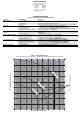
The chart (Table 1) will assist you in selecting the proper bevel and miter settings for common
compound miter cuts. To use the chart, select the desired angle “A” (Figure 15) of your project
and locate that angle on the appropriate arc in the chart. From that point follow the chart straight
down to find the correct bevel angle and straight across to find the correct miter angle.
Set your saw to the prescribed angles and make a few trial cuts. Practice fitting the cut pieces
together until you develop a feel for this procedure and feel comfortable with it.
Example: To make a four-sided box with 26° exterior angles (Angle A, Figure 15), use the upper
right arc. Find 26° on the arc scale. Follow the horizontal intersecting line to either side to get
miter angle setting on saw (42°). Likewise, follow the vertical intersecting line to the top or bottom
to get the bevel angle setting on the saw (18°). Always try cuts on a few scrap pieces of wood to
verify settings on saw.