


66
Adjustments
WARNING: To reduce the risk of serious personal injury, turn off the
tool and disconnect it from the power source before attempting to move
it, change accessories or make any adjustments accept as written in laser
adjustment instructions.
NOTE: Your miter saw is fully and accurately adjusted at the factory at the
time of manufacture. If readjustment due to shipping and handling or any
other reason is required, follow the steps below to adjust your saw.
Once made, these adjustments should remain accurate. Take a little time
now to follow these directions carefully to maintain the accuracy of which
your saw is capable.
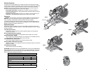
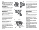
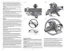
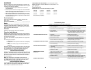
MITER SCALE ADJUSTMENT (FIG. 5)
Place a square against the saw’s fence and blade, as shown. (Do not
touch the tips of the blade teeth with the square. To do so will cause an
inaccurate measure ment.) Loosen the miter lock handle and swing the
miter arm until the miter latch locks it at the 0 miter position. Do not
tighten the lock handle. If the saw blade is not exactly
perpendicular to the fence, loosen the four screws that hold the miter
scale to the base and move the scale left or right until the blade is
perpendicular to the fence, as measured with the square. Retighten the
four screws. Pay no attention to the reading of the miter pointer at this
time.
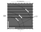
MITER POINTER ADJUSTMENT (FIG. 6)
Loosen the miter lock handle to move the miter arm to the zero position.
With the miter lock handle loose allow the miter latch to snap into place
as you rotate the miter arm to zero. Observe the pointer and miter scale
shown in Figure 6. If the pointer does not indicate exactly zero, loosen the
screw holding the pointer in place, reposition the pointer and tighten the
screw.
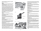
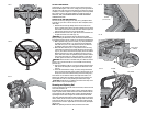
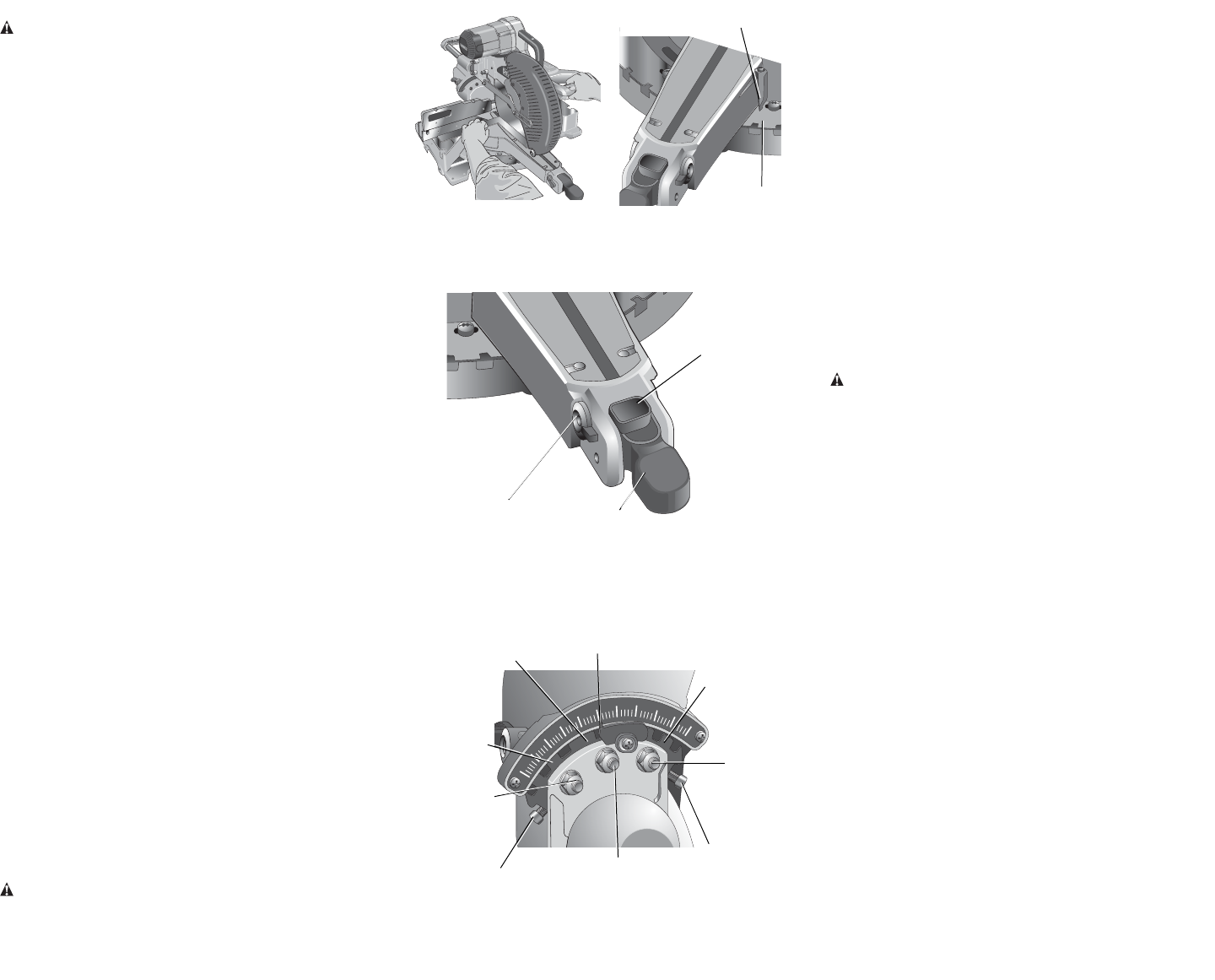
BEVEL SQUARE TO TABLE ADJUSTMENT (FIG. 8)
To align the blade square to the table, lock the arm in the down position.
Place a square against the blade and table taking care to have the square
not touch a blade tooth. Loosen the bevel lock handle and ensure the
bevel latch has firmly snapped into place at 0º. If the saw blade is not
exactly perpendicular to the table, loosen the three nuts which hold the
bevel detent plates to the table. Adjust the center nut to allow slight drag
between it and the table. Gently tap the motor or the belt cover to move
the upper assembly until the blade is square to the table. Tighten the
center nut. The 45º bevel stops require adjustment after the bevel square
to table adjustment is complete.
BEVEL POINTER (FIG. 8)
If the bevel pointer does not indicate zero, loosen the screw that holds it in
place and move it as necessary.
BEVEL STOP 45º RIGHT AND LEFT ADJUSTMENT (FIG. 8)
Your saw has two 45º bevel adjustments, one for the right, and one for
the left. The procedure is the same for each.
To align the 45º stops, lock the arm in the down position. Place a speed
square against the blade and table taking care to have the square not
touch a blade tooth. Loosen the bevel lock lever and ensure the bevel
latch has firmly snapped into place at 45º. If the saw blade is not 45º
to the table, loosen the nut which holds the 45 bevel latch plate to the
table. Rotate the adjustment screw counterclockwise one or two turns
so that the blade is less than 45º to the table. Turn the adjustment screw
clockwise until the blade is 45º to the table. Tighten the lock nut.
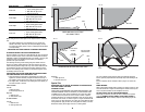
FENCE ADJUSTMENT (FIG. 9)
WARNING: To reduce the risk of serious personal injury, turn off the
tool and disconnect it from the power source before attempting to move
it, change accessories or make any adjustments accept as written in laser
adjustment instructions.
In order that the saw can bevel to a full 48º left or right, one of the fences
can be adjusted to provide clearance. To adjust the fences, loosen a
plastic knob and slide the fence outward. Make a dry run with the saw
turned off and check for clearance. Adjust the fence to be as close to
the blade as practical to provide max imum workpiece support, without
interfering with arm up and down movement. Tighten knob securely. When
the bevel operations are complete, don’t forget to relocate the fence.
NOTE: The guide groove of the fences can become clogged with sawdust.
If you notice that it is becoming clogged, use a stick or some low
pressure air to clear the guide groove.
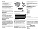
AUTOMATIC ELECTRIC BRAKE
Your saw is equipped with an automatic electric blade brake which stops
the saw blade within 5 seconds of trigger release. This is not adjustable.
On occasion, there may be a delay after trigger release to brake
engagement. On rare occasions, the brake may not engage at all and the
blade will coast to a stop.
If a delay or “skipping” occurs, turn the saw on and off 4 or 5 times. If
the condition persists, have the tool serviced by an authorized D
EWALT
service center.
Always be sure the blade has stopped before removing it from the kerf.
The brake is not a substitute for guards or for ensuring your own safety by
giving the saw your complete attention.
GUARD ACTUATION AND VISIBILITY
CAUTION: Risk of personal injury. Keep thumb underneath handle when
pulling handle down otherwise thumb may be pinched between handle
and moving lower guard. The handle is placed close to the guard for
special cuts.
The blade guard on your saw has been designed to automatically raise
when the arm is brought down and to lower over the blade when the arm
is raised.
The guard can be raised by hand when installing or removing saw
blades or for inspection of the saw. NEVER RAISE THE BLADE GUARD
MANUALLY UN LESS THE SAW IS TURNED OFF.
NOTE: Certain special cuts of large material will require that you manually
raise the guard. See page 11.
The front section of the guard is louvered for visibility while cutting.
Although the louvers dramatically reduce flying debris, they are openings
in the guard and safety glasses should be worn at all times when viewing
through the louvers.
KERF PLATE ADJUSTMENT
To adjust the kerf plates, loosen the screws holding the kerf plates in
place. Adjust so that the kerf plates are as close as possible without
interfering with the blade’s movement.
RAIL GUIDE ADJUSTMENT
Periodically check the rails for any play or clearance. The right rail can be
adjusted with the set screw shown in Figure 4. To reduce clearance, use
a 4 mm hex wrench and rotate the set screw clockwise gradually while
sliding the saw head back and forth. Adjust the clearance to be as small
as possible without causing any slide resistance.
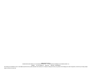
MITER LOCK ADJUSTMENT
The miter lock rod should be adjusted if the table of the saw can be
moved when the miter lock is locked down. To adjust the miter lock
handle, put the miter lock handle in the up, unlocked position. Using a
13 mm open end wrench, loosen the lock nut on the miter lock rod
(Fig. 10A). Using a slotted screwdriver, tighten the miter lock rod by
turning it clockwise as shown in Figure 10A. Turn the lock rod until it
is snug, then turn counterclockwise one turn. To ensure the miter lock
FIG. 6
MITER
SCALE
MITER
POINTER
FIG. 5
FIG. 8
RIGHT 45º BEVEL
LATCH PLATE
LEFT 45º BEVEL
LATCH PLATE
RIGHT 45º
BEVEL PLATE
LOCK NUT
BEVEL POINTER
LEFT 45º BEVEL
ADJUSTMENT
SCREW
RIGHT 45º BEVEL
ADJUSTMENT SCREW
0º BEVEL LOCK
NUT
0º BEVEL LATCH PLATE
LEFT 45º
BEVEL PLATE
LOCK NUT
FIG. 7
MITER LOCK
HANDLE
MITER LATCH
BUTTON
MITER LATCH
OVERRIDE