


7
when the bevel lock handle is tightened. To adjust the bevel lock handle,
remove the screw in the center of the handle. Carefully pry off the handle
using a flat bladed screwdriver. Reorient and install the handle such that it
will hold the bevel when tightened. Install and tighten screw.
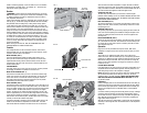
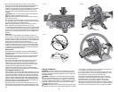
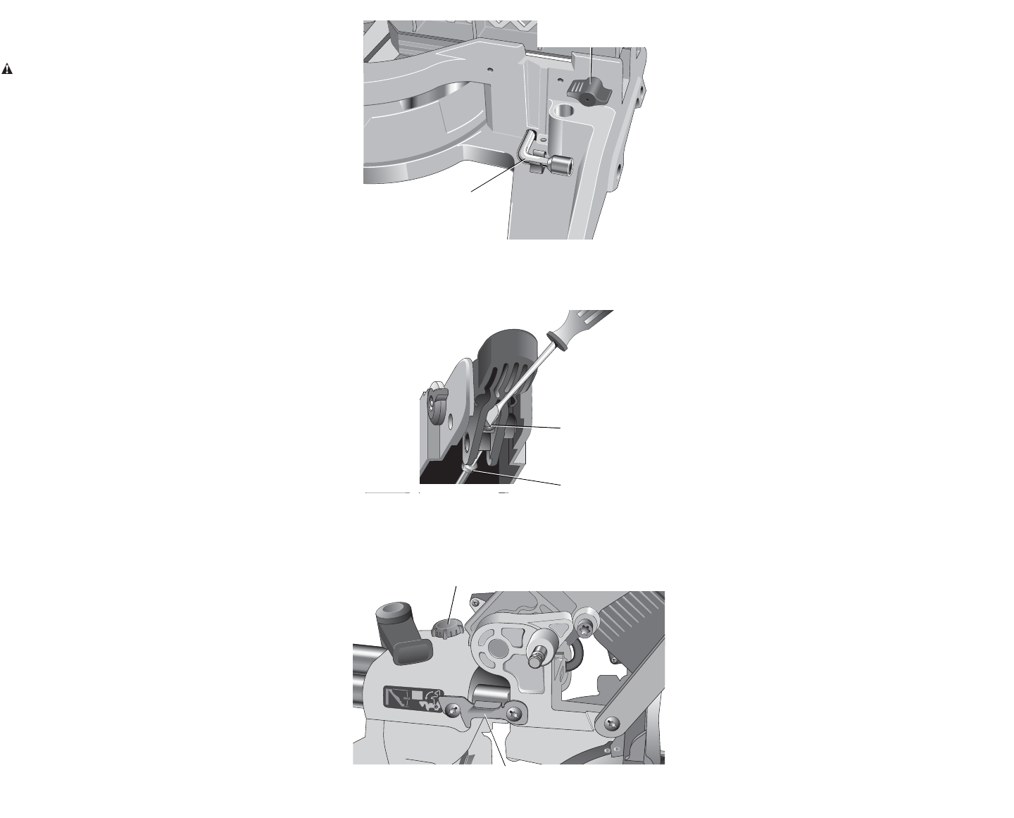
SLIDE STOP (FIG. 10B)
The slide stop control positions your saws rails so that the largest
possible verticle moldings can be cut. ALWAYS TIGHTEN THE RAIL LOCK
KNOB WHEN USING THE SLIDE STOP TO PREVENT THE SLIDE SYSTEM
FROM MOVING UNINTENTIONALLY
RAIL LOCK KNOB (FIG. 4)
The rail lock knob allows you to lock the saw head firmly to keep it from
sliding on the rails. This is necessary when making certain cuts or when
transporting the saw.
GROOVING STOP (FIG. 4)
The grooving stop allows for groove cutting. Flipping the lever toward the
front of the saw and adjusting the thumbscrew changes the depth of the
groove cut. Flipping the lever toward the rear of the saw bypasses the
grooving stop.
HEAD LOCK-DOWN PIN (FIG. 4)
To lock the saw head in the down position, push the head down, push the
pin in and release the saw head. This will hold the saw head safely down
for moving the saw from place to place. To release, press the saw head
down and pull the pin out.
Operation
Plug the saw into any household 50 Hz power source. Refer to the
nameplate for voltage. Be sure the cord will not interfere with your work.
SWITCH
To turn the saw on, depress the trigger switch. To turn the tool off,
release the switch. Allow the blade to spin up to full operating rpm before
making the cut. Release the trigger switch and allow the brake to stop the
blade before raising the saw head. There is no provision for locking the
switch on, but a hole is provided in the trigger for insertion of a padlock
to lock the saw off.
CUTTING WITH YOUR SAW
If the slide feature is not used, ensure the saw head is pushed back as far
as possible and the rail lock knob is tightened. This will prevent the saw
from sliding along its rails as the workpiece is engaged.
NOTE: Although this saw will cut wood and many non-ferrous materials,
we will limit our discussion to the cutting of wood only. The same
guidelines apply to the other mat erials. DO NOT CUT FERROUS (IRON
AND STEEL) MAT ERIALS OR MASONRY WITH THIS SAW. Do not use
any abrasive blades.
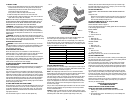
CROSSCUTS
Cutting of multiple pieces is not recommended but can be done safely by
ensuring that each piece is held firmly against the table and fence. When
the saw comes up to speed (about 1 second) lower the arm smoothly and
slowly to cut through the wood. Let the blade come to a full stop before
raising arm.
A crosscut is made by cutting wood across the grain at any angle. A straight
crosscut is made with the miter arm at the zero degree position. Set and
lock the miter arm at zero, hold the wood firmly on the table and against the
fence. With the rail lock knob tightened, turn on the saw by squeezing the
trigger switch shown in Figure 4.
When the saw comes up to speed (about 1 second) lower the arm smoothly
and slowly to cut through the wood. Let the blade come to a full stop before
raising arm.
7
handle is functioning properly, re-lock the miter lock to a non-detented
measurement on the miter scale – for example, 34º – and ensure the
table will not rotate. Tighten lock nut.
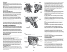
Brushes
WARNING: To reduce the risk of serious personal injury, turn off the
tool and disconnect it from the power source before attempting to move
it, change accessories or make any adjustments accept as written in
laser adjustment instructions.
Inspect carbon brushes regularly by unplugging tool, removing the motor
end cap (Fig. 4), lift the brush spring and withdraw the brush assembly.
Keep brushes clean and sliding freely in their guides. Always replace
a used brush in the same orientation in the holder as it was prior to its
removal. Carbon brushes have varying symbols stamped into their sides,
and if the brush is worn down to approximately 12.7 mm (1/2"), the
spring will no longer exert pressure and they must be replaced. Use only
identical D
EWALT brushes. Use of the correct grade of brush is essential
for proper operation of electric brake. New brush assemblies are available
at DEWALT service centers. The tool should be allowed to “run in” (run
at no load) for 10 minutes before use to seat new brushes. The electric
brake may be erratic in operation until the brushes are properly seated
(worn in). Always replace the brush inspection cap after inspection or
servicing the brushes.
While “running in” DO NOT TIE, TAPE, OR OTHER WISE LOCK THE
TRIGGER SWITCH ON. HOLD BY HAND ONLY.
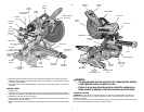
Controls
Your compound miter saw has several main controls, which will be
discussed briefly here. For more information on these controls, see the
respective sections earlier in the manual.
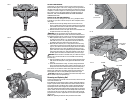
MITER CONTROL (FIG. 7)
The miter adjustment/lock handle and detent trigger allows you to
miter your saw to 60 left and 50 right. To miter the saw, lift the miter
adjustment/lock handle, push the miter latch button and set the miter
angle desired on the miter scale. Push down on the lock handle to lock
the saw table in place.
TRIGGER SWITCH
The trigger switch (Fig. 4) turns your saw on and off. A hole is provided
in the trigger for insertion of a padlock to secure the saw.
MITER LATCH OVERRIDE (FIG. 7)
The miter latch override allows your saw to override the common stop
angles. Your saw has two miter latch override knobs, one on each side
of the miter control. To override the common stop angles, rotate the
miter latch knobs downward. The knobs will return to the off position
automatically if the miter latch button is pushed.
BEVEL CONTROL (FIG. 8)
The bevel latch levers and bevel lock handle allow you to bevel the saw to
48º left and right. Your saw has two bevel latch levers, one on either side
of the rear support housing. Only one needs to be used to move the bevel
to either direction. The bevel lock handle is on top of the rear support
housing. To bevel the saw, loosen the bevel lock handle. Lift one of the
levers to approximately 45 º and set the bevel angle desired on the bevel
scale. Two bevel scales are provided for convenience. Lock the bevel
lock handle to lock the bevel in place. The bevel latch levers can be lifted
vertically to override the common stop angles.
The bevel lock handle is designed to have a limited rotation amount. The
handle can be reoriented to compensate for normal wear. The bevel
lock handle should be reoriented if the bevel of the saw can be moved
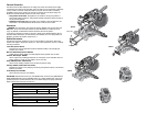
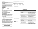
FIG. 9
LEFT-SIDE
FENCE KNOB
BLADE WRENCH
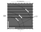
FIG. 10A
MITER LOCK ROD
LOCK NUT
FIG. 10B
SLIDE STOP
RAIL LOCK KNOB