


English
6
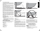
45º bevel - Right
Max. Height 1.2" (30 mm) Result Width 11.9" (302 mm)
Max. Width 12.6" (320 mm) Result Height 0.9" (22 mm)
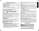
Your saw is capable of cutting baseboard moldings 0.8" (20 mm) thick by 4.75" (120 mm)
tall.
NOTE: Your saw is capable of cutting the following once a special setup procedure is
followed (see Special Cuts).
0º miter height 1.5 (38 mm) width 15.4 (391 mm)
45º miter height 1.5 (38 mm) width 11.3 (287 mm)
DRIVE
120 Volt Motor
1600 Watts In 15 Amp Motor
4000 RPM Cut Helical Gears
Multi-V Belt Roller Bearings
Automatic Electric Brake Carbide Blade
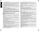
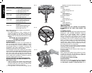
Familiarization
FIG. 1
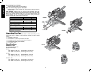
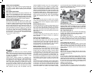
Your miter saw is fully assembled in the car ton. Open the
box and slide the saw out, as shown in Figure 1.
Place the saw on a smooth, flat surface such as a
workbench or strong table.
Examine the two figures on Page 7 to become familiar
with the saw and its various parts. The section on adjus-
tments will refer to these terms and you must know what
and where the parts are.
CAUTION: Risk of personal injury. Keep thumb
underneath handle when pulling handle down otherwise
thumb may be pinched between handle and moving lower
guard.
The handle is placed close to the guard for special cuts.
Press down lightly on the operating handle and pull out the lock
FIG. 2
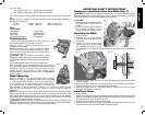
down pin. Gently release the downward pressure and hold the arm
allowing it to rise to its full height. Use the lock down pin when
carrying the saw from one place to another. Always use the
carrying handle to transport the saw or the hand indentations
shown in Figure 2.
Bench Mounting
Holes are provided in all 4 feet to facilitate bench mounting,
as shown in Figure 4. (Two different sized holes are provided
to accommodate different sizes of screws. Use either hole, it
is not necessary to use both.) Always mount your saw firmly
to a stable surface to prevent movement. To enhance the
tool’s portability, it can be mounted to a piece of 1/2" (12.7 mm) or thicker plywood
which can then be clamped to your work support or moved to other job sites and
reclamped.
NOTE: If you elect to mount your saw to a piece of plywood, make sure that the mounting
screws don’t protrude from the bottom of the wood. The plywood must sit flush on the
work support. When clamping the saw to any work surface, clamp only on the clamping
bosses where the mounting screw holes are located. Clamping at any other point will surely
interfere with the proper operation of the saw.
CAUTION: To prevent binding and inaccuracy, be sure the mounting surface is not
warped or otherwise uneven. If the saw rocks on the surface place a thin piece of material
under one saw foot until the saw sits firmly on the mounting surface.
IMPORTANT SAFETY INSTRUCTIONS
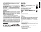
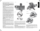
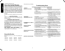
Changing or Installing a New Saw Blade (Fig. 3)
WARNING: To reduce the risk of serious personal injury, turn off the tool and disconnect
it from the power source before attempting to move it, change accessories or make any
adjustments accept as written in laser adjustment instructions.
CAUTION:
• Never depress the spindle lock button
A
B
D
FIG. 3
while the blade is under power or
coasting.
• Do not cut ferrous metal (containing
iron or steel) or masonry or fiber
cement product with this miter saw.
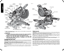
Removing the Blade
1. Unplug the saw.
2. Raise the arm to the upper position
and raise the lower guard (A) as far
as possible.
3. Loosen, but do not remove guard
bracket screw (B) until the bracket
can be raised far enough to access
the blade screw. Lower guard will remain raised due to the position of the guard bracket
screw.
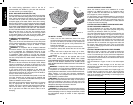
C
FIG. 3A
FIG. 3B
E
F
G
I
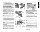
4. Depress the spindle lock button (C) while carefully rotating the saw blade by hand until
the lock engages.
5. Keeping the button depressed, use the other hand and the wrench provided (D) to
loosen the blade screw. (Turn clockwise, left-hand threads)
6. Remove the blade screw (E), outer blade clamp (F) and blade (G). The inner blade
clamp (I), may be left on the spindle.
Installing a Blade
1. Unplug the saw.
2. With the arm raised, the lower guard held open and the guard bracket raised, place the
blade on the spindle and against the inner blade clamp with the teeth at the bottom of
the blade pointing toward the back of the saw.
3. Assemble the outer blade clamp onto the spindle.
4. Install the blade screw and, engaging the spindle lock, tighten the screw firmly with
wrench provided. (Turn counterclockwise, left-hand threads.)