


English
11
NOTE: Circuit breaker overload is often the result of dull knives.
Change your knives on a regular basis to avoid tripping your
breaker. Check your knives before re-setting the circuit breaker and
continuing to plane.
See the Troubleshooting Guide on page 14 for additional information
on circuit breaker trips.
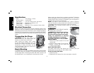
Replacing the Drive Belt
Drive belts are available at extra cost at DEWALT authorized service
centers. Replacement of the drive belt should be performed by
qualified service personnel.
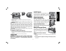
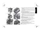
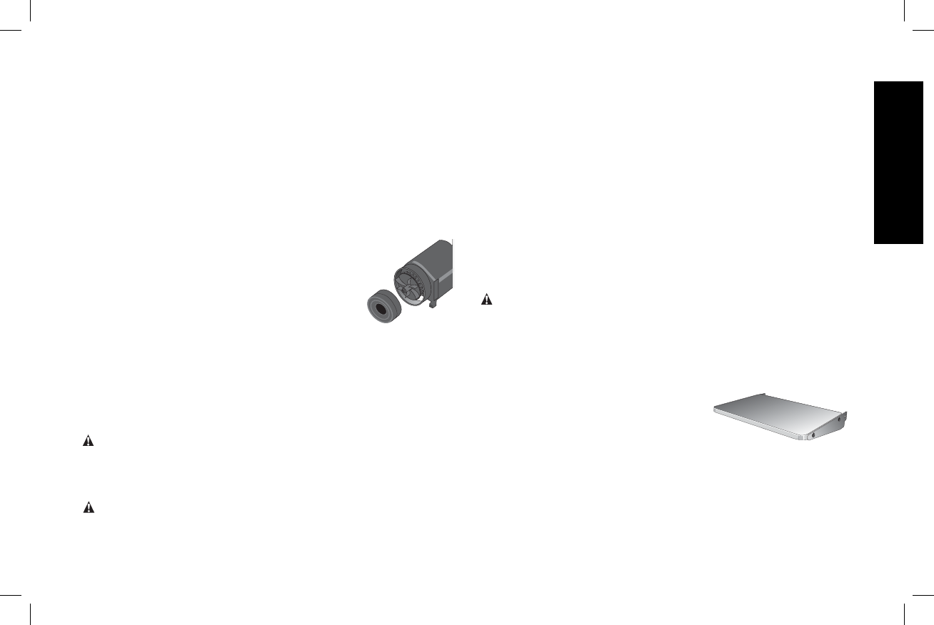
Chip Ejection Fan
The chip ejection fan on your planer should
be cleaned or cleared of debris periodically.
NOTE: TURN OFF AND UNPLUG THE PLANER
PRIOR TO ACCESSING THE CHIP EJECTION
FAN.
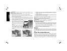
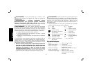
TO ACCESS THE FAN
1. Remove the top cover of the planer with the T-wrench.
2. Remove the dust shroud (Fig. 2, 3) and place it aside.
3. Remove the screws around the fan housing.
4. Remove the fan housing and place it aside as shown. The fan will
now be exposed for cleaning.
See the Troubleshooting Guide, page 14, for additional information.
WARNING: Be sure to properly attach the fan housing and
assemble the shroud and top cover correctly before using your planer
again.
Accessories
WARNING: Since accessories, other than those offered by
D
EWALT, have not been tested with this product, use of such
accessories with this tool could be hazardous. To reduce the risk of
injury, only DEWALT, recommended accessories should be used with
this product.
Recommended accessories for use with your tool are available at
extra cost from your distributor or local service center.
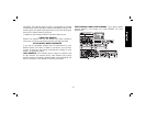
Four accessories are available for the DW735 Thickness Planer.
• DW7350 Mobile Stand
• DW7351 Folding Tables
• DW7352 13" Knives
• DW7353 Chip Ejection Accessory
If you need any assistance in locating these accessories, please
contact D
EWALT Industrial Tool Co., 701 East Joppa Road, Baltimore,
MD 21286 or call 1-800-4-D
EWALT (1-800-433-9258) or www.
dewalt.com
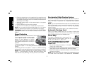
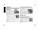
DW7351 Accessory Folding Tables
WARNING: For your own safety, read the tool instruction manual
before attaching the tables. Failure to heed these warnings may
result in personal injury and serious damage to the planer and the
accessory. When servicing this tool, use only identical replace ment
parts. Have damaged cords replaced by an authorized service
center.
Your DW7351 folding table box should include:
2 folding tables 4 cap screws
4 springs 4 nuts
4 stepped bolts
SET-UP AND INSTALLATION OF BASE
HARDWARE
1. Place planer on a secure table or workbench. Position planer so
the front 3-4" of the base can be accessed from the underside.
2. Secure the rear of the planer to the table/bench with nails or
screws to prevent it from tilting or falling from the table.