


English
6
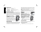
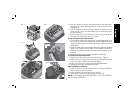
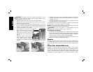
3. Crank the carriage down on the ma terial until the material removal
bar engages the wood. You will see the red arrow begin to move
up the scale indicating the amount of material to be removed with
the carriage at that height.
4. Adjust the carriage height until the desired depth of cut appears
on the gauge.
5. Pull the material out from under the carriage.
6. Turn the unit on and feed your material into the cutter head.
NOTE: Do not exceed the recommended depth of cut for various
widths of material recommended on the material removal gauge.
WARNING: DO NOT SWITCH THE UNIT ON WITH THE MATERIAL
POSITIONED UNDER THE CARRIAGE. SERIOUS INJURY COULD
RESULT.
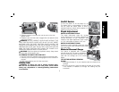
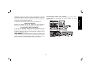
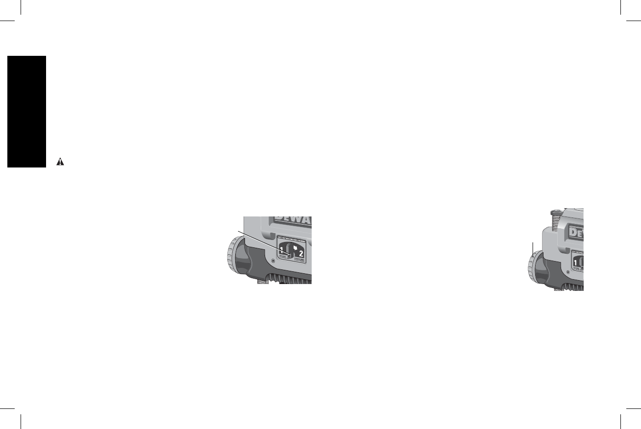
Speed Selection
NOTE: ONLY SWITCH SPEEDS WHEN THE PLANER IS RUNNING.
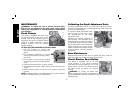
Your planer has the ability to feed material
P
at two different speeds. The two-speed
feature (P) was designed to improve
efficiency when planing and to provide the
best possible surface finish to a variety of
materials.
To remove material thickness more quickly,
set the unit at speed “2”. This setting delivers 96 cuts per inch to the
material.
For finishing, set the unit to speed “1”. Speed “1” is ideal for ensuring
the finest finish on the last pass before your final thickness is achieved.
NOTE: When planing particularly hard or figured species of wood,
speed “1” is recommended. The slower feed rate will reduce knife
wear and tear-out by delivering 179 cuts per inch to the material.
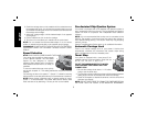
Fan-Assisted Chip Ejection System
Your planer is equipped with a fan-assisted chip ejection system to
aid in exhausting chips from the unit. The fan-assisted chip ejection
system will work in conjunction with independent dust collection
systems.
NOTE: It is not recommended that a shop vac be connected to the
DW735. The capacity of most vacs does not support the volume of
chips ejected during planing. The vacuum hose may clog stopping
the flow of chips.
See the Troubleshooting Guide, page 14, for additional information.
Automatic Carriage Lock
There is no manual carriage lock on your planer. A device that
automatically minimizes the movement that causes snipe during
planing is designed into the four threaded posts.
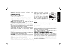
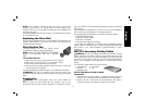
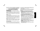
Turret Stop
Q
Your planer is equipped with a turret stop (Q) for
repetitive planing at pre-set depths. Stops are set
at 1/8", 1/4", 1/2", 3/4", 1", and 1-1/4".
TO SET THE MINIMUM DEPTH TO WHICH
THE CARRIAGE CAN TRAVEL WITH THE
TURRET STOP
1. Be sure the carriage is set above 1-1/4" before
trying to set the turret stop.
2. Turn the dial on the front left of the planer until the desired thickness
setting aligns with the red indicator then lower the carriage.
3. Plane the workpiece at desired increments until the correct final
thickness is achieved.
NOTE: DO NOT USE FORCE TO CRANK THE CARRIAGE BELOW
THE LEVEL THAT THE TURRET STOP INDICATES. PERMANENT