


ENGLISH
6
Electrical Safety
The electric motor has been designed for one
voltage only. Always check that the power supply
corresponds to the voltage on the rating plate.
Your DEWALT tool is double insulated in
accordance with EN 60745; therefore no
earth wire is required.
If the supply cord is damaged, it must be replaced
by a specially prepared cord available through the
D
EWALT service organisation.
Mains Plug Replacement
(Middle East and Africa)
If a new mains plug needs to be fitted:
• Safely dispose of the old plug.
• Connect the brown lead to the live terminal in
the plug.
• Connect the blue lead to the neutral terminal.
WARNING: No connection is to be
made to the earth terminal.
Follow the fitting instructions supplied with good
quality plugs. Recommended fuse: 13 A.
Using an Extension Cable
If an extension cable is required, use an approved
extension cable suitable for the power input of this
tool (see Technical Data). The minimum conductor
size is 1 mm
2
; the maximum length is 30 m.
When using a cable reel, always unwind the cable
completely.
ASSEMBLY AND ADJUSTMENTS
WARNING: To reduce the risk of
injury, turn unit off and disconnect
machine from power source before
installing and removing accessories,
before adjusting or changing set-
ups or when making repairs. Be sure
the trigger switch is in the OFF position.
An accidental start-up can cause injury.
Bench Mounting
1. Mark the position of the four mounting holes
provided in the base of the machine on the
workbench.
2. Drill appropriate sized hole at each of the
marked positions.
3. Place the machine on the workbench and insert
a 6mm hex head bolt with washer through
each mounting hole in the base and into each
of the holes drilled in the workbench.
4. Place a nut on each of the bolts and securely
tighten the nuts.
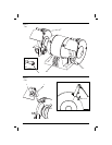
Mounting of Spark Guard (fi g. 2)
The spark guard offers additional protection from
sparks and must be used whenever possible.
NOTE: Spark guards are not designed to replace
safety glasses.
1. Loosen screw (d) (do not remove it).
2. Slide spark guard (a) onto bracket.
3. Position the spark guard at a distance of
approx. 2mm from the grinding wheel. Tighten
screw (d).
NOTE: Regularly check the distance between
spark guard and the grinding wheel and adjust,
if necessary. Replace the grinding wheel if spark
guard (a) can no longer be adjusted to the maximum
distance of 2mm.
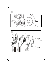
Installing Tool Rest (fi g. 3)
WARNING: Use the washers and
screws supplied. Longer screws may
interfere with the movement of the
grinding wheel.
1. Use the supplied bolts, washers, spacers and
lock nuts to secure the tool rests (c) in place.
2. Position the tool rest at a distance of
approximately 2mm from the grinding wheel.
Regularly check the distance between tool
rest (c) and the grinding wheel and adjust, if
necessary.
OPERATION
Instructions for Use
WARNING: Always observe the safety
instructions and applicable regulations.
WARNING: To reduce the risk of
injury, turn unit off and disconnect
machine from power source before
installing and removing accessories,
before adjusting or changing set-
ups or when making repairs. Be sure
the trigger switch is in the OFF position.
An accidental start-up can cause injury.
WARNING: Never use a bench grinder
if it is not firmly fastened to a work
bench or rigid frame. Before turning the
grinder on, put on safety glasses.