


Chucks
WARNING: Burn Hazard. ALWAYS wear gloves when changing bits. Accessible metal parts
on the tool and bits may get extremely hot during operation. Small bits of broken material may
damage bare hands.
WARNING: Do not attempt to tighten drill bits (or any other accessory) by gripping the front
part of the chuck and turning the tool on. Damage to the chuck and personal injury may result.
A
lways lock off trigger switch when changing accessories.
KEYLESS DOUBLE SLEEVE CHUCK (FIG.
7)
(
DW
927, D
W928,
D
W959–T
ype 1)
Your tool features a keyless chuck for greater convenience.To insert a drill bit or other accessory,
f
ollow the steps listed below.
1
. Lock the trigger in the OFF position as previously described.
2. Grasp the rear half of the chuck with one hand and use your other hand to rotate the front
h
alf counterclockwise, as shown. Rotate far enough so that the chuck opens sufficiently to
a
ccept the desired accessory
.
3. Insert the bit or other accessory about 3/4" (19 mm) the chuck and tighten securely by holding
t
he rear half of the chuck and rotating the front portion in the clockwise direction.
T
o release the accessor
y
,
repeat steps 1 and 2 listed abo
v
e
.
K
EYLESS SINGLE SLEEVE CHUCK (FIG. 8)
(DW959–Type 2)
Your tool features a keyless chuck with one rotating sleeve for one-handed operation of the
chuc
k. To insert a drill bit or other accessory, follow these steps.
1. Lock the trigger in the OFF position as previously described.
2. Grasp the black sleeve of the chuck with one hand and use the other hand to secure the
tool.
R
otate the sleev
e countercloc
kwise f
ar enough to accept the desired accessor
y.
3.
Inser
t the accessor
y about 3/4" (19 mm) into the chuc
k
and tighten securely by
rotating the
c
huck slee
v
e cloc
kwise with one hand while holding the tool with the other. Your tool is
e
quipped with an automatic spindle lock mechanism.This allows you to open and close the
c
huck with one hand.
To release the accessory, repeat steps 1 and 2 listed above.
B
e sure to tighten chuck with one hand on the chuck sleeve and one hand holding the tool for
m
aximum tightness.
Operation as a Drill
T
ur
n the collar to the dr
ill bit symbol.
Install and tighten the desired drill bit in the chuck. Select
t
he desired speed/torque range using the dual range gear shifter to match the speed and torque
to the planned operation. Follow these instructions for best results when drilling.
D
RILLING
1. Use sharp drill bits only. For WOOD, use twist drill bits, spade bits, power auger bits, or hole
saws. For METAL, use high speed steel twist drill bits or hole saws. For MASONRY, such as
br
ic
k, cement, cinder b
loc
k, etc., use carbide-tipped bits
.
2
. Be sure the material to be drilled is anchored or clamped firmly. If drilling thin material, use a
“back-up” block to prevent damage to the material.
3
. Always apply pressure in a straight line with the bit. Use enough pressure to keep the drill bit
b
iting, but do not push hard enough to stall the motor or deflect the bit.
4.
H
old tool firmly to control the twisting action of the dr
ill.
5.
IF DRILL STALLS, it is usually because it is being overloaded. RELEASE TRIGGER
I
MMEDIAT
ELY
,
r
emov
e dr
ill bit from work, and determine cause of stalling.
D
O NOT
CLICK
TRIGGER OFF AND ON IN AN A
TTEMPT
T
O STAR
T A ST
ALLED DRILL – THIS CAN
DAMAGE THE DRILL.
6.
T
o minimiz
e stalling upon breaking through the material, reduce pressure on drill and ease
the bit through the last fractional part of the hole.
7.
Keep the motor running when pulling the bit back out of a drilled hole.This will help prevent
jamming.
8. With variable speed drills there is no need to center punch the point to be drilled. Use a slow
speed to start the hole and accelerate by squeezing the trigger harder when the hole is deep
enough to dr
ill without the bit skipping out.
Operate at full-on after starting the bit.
DRILLING IN
W
OOD
Holes in wood can be made with the same twist drills used for metal. These bits may overheat
unless pulled out frequently to clear chips from the flutes. For larger holes, use low speed wood
bits.Work that is likely to splinter should be backed up with a block of wood.
DRILLING IN MET
ALS
Use a cutting lubr
icant when dr
illing metals
.
The exceptions are cast iron and brass which should
be dr
illed dr
y. The cutting lubricants that work best are sulphurized cutting oil or lard oil; bacon
grease will also serve the purpose.
DRILLING MASONRY
Use carbide tipped masonr
y bits at low speeds. Keep even force on the drill but not so much that
you crack the brittle materials. A smooth, even flow of dust indicates the proper drilling rate.
Operation as a Screwdriver
Select the desired speed/torque range using the dual range gear shifter on the top of tool to
match the speed and torque to the planned operation.
Insert the desired fastener accessory into the chuck as you would any drill bit.Make a few practice
runs in scrap or unseen areas to determine the proper position of the clutch collar.
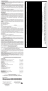
MAXIMUM RECOMMENDED CAP
ACITIES
DW927, DW928, DW929 DW959
W
OOD 1-1/2" (38 mm) 1-1/2" (38 mm)
STEEL
3/8" (10 mm)
1/2" (13 mm)
CONCRETE
3/16" (4.8 mm)
1/4" (6.4 mm)
MAINTENANCE
W
ARNING:
T
o reduce the risk of serious per
sonal injur
y
,
turn tool off and disconnect
tool from power source before making any adjustments or removing/installing
attachments or accessories.
Cleaning
W
ARNING:
Blo
w dirt and dust out of all air vents with dry air at least once a week.Wear safety
glasses when performing this. Never use solvents or other harsh chemicals for cleaning the non-
metallic parts of the tool.These chemicals may weaken the plastic materials used in these parts.
Use a cloth dampened only with water and mild soap. Do not use gasoline, turpentine, lacquer
or paint thinner, dry cleaning fluids or similar products. Never let any liquid get inside the tool;
never immerse any part of the tool into a liquid.
CHARGER CLEANING INSTRUCTIONS
WARNING: Shock hazard.Disconnect the charger from the AC outlet before cleaning.Dirt and
grease may be removed from the exterior of the charger using a cloth or soft non-metallic brush.
Do not use w
ater or an
y cleaning solutions
.
Accessories
WARNING: Since accessories, other than those offered by DEWALT have not been tested with
this product, use of such accessories with this tool could be hazardous. To reduce the risk of
injury, only D
EWALT, recommended accessories should be used with this product.
i
n the battery pack are equalized.The battery pack is ready for use and can be removed at any
t
ime during the Tune-Up™ Mode.
4. Once the Automatic Tune-Up™ Mode is complete the charger will transition to a maintenance
charge; the indicator light shuts off when the Automatic Tune-Up™ Mode is complete.
S
AVE THESE INSTRUCTIONS FOR FUTURE USE
Chargers
Your battery can be charged in DEWALT 1 Hour Chargers, 15 Minute Chargers or Vehicular
1
2 Volt Charger.Be sure to read all safety instructions before using your charger.Consult the chart
at the end of this manual for compatibility of chargers and battery packs.
Charging Procedure
DANGER: Electrocution hazard. 120 volts are present at charging terminals. Do not probe with
conductive objects.
1. Plug the charger into an appropriate outlet before inserting battery pack.
2
. Insert the battery pack into the charger, as shown in Figure 3, making sure the pack is fully
seated.The red (charging) light will blink continuously indicating that the charging process has
started.
3. The completion of charge will be indicated by the red light remaining ON continuously. The
pack is fully charged and may be used at this time or left in the charger.
Indicator Light Operation
Charge Indicators
Some chargers are designed to detect certain problems that can arise with battery packs.Problems
are indicated by the red light flashing at a fast rate. If this occurs, re-insert battery pack into the
charger.If the problem persists, try a different battery pack to determine if the charger is OK. If the
new pack charges correctly, then the original pack is defective and should be returned to a service
center or other collection site for recycling.If the new battery pack elicits the same trouble indication
a
s the original, have the charger tested at an authorized service center.
HOT/COLD PACK DELAY
S
ome chargers have a Hot/Cold Pack Delay feature: when the charger detects a battery that is
h
ot, it automatically starts a Hot Pack Delay, suspending charging until the battery has cooled.
After the battery has cooled, the charger automatically switches to the Pack Charging mode.This
feature ensures maximum battery life.The red light flashes long, then short while in the Hot Pack
Delay mode.
P
ROBLEM POWER LINE
Some chargers have a Problem Power Line indicator. When the charger is used with some
portable power sources such as generators or sources that convert DC to AC, the charger may
temporarily suspend operation,
flashing the red light with two fast blinks followed by a pause.
This indicates the power source is out of limits.
LEAVING THE BATTERY PACK IN THE CHARGER
The charger and battery pack can be left connected with the red light glowing indefinitely. The
charger will keep the battery pack fresh and fully charged.
N
OTE:
A
battery pack will slowly lose its charge when kept out of the charger. If the battery pack
has not been kept on maintenance charge, it may need to be recharged before use.A battery pack
may also slowly lose its charge if left in a charger that is not plugged into an appropriate AC
source
.
W
EAK BA
TTER
Y P
ACKS:
C
hargers can also detect a we
ak battery
.
Such batteries are still
usab
l
e bu
t should not be expected to perform as much work. In such cases, about 10 seconds
after batter
y insertion, the charger will beep rapidly 8 times to indicate a weak battery condition.
The charger will then go on to charge the battery to the highest capacity possible.
Important Charging Notes
1. Longest life and best performance can be obtained if the battery pack is charged when the
air temperature is between 65°F and 75°F (18°- 24°C). DO NOT charge the battery pack in
an air temperature below +40°F (+4.5°C), or above +105°F (+40.5°C).This is important and
w
ill prevent serious damage to the battery pack.
2.
T
he charger and battery pack may become warm to touch while charging. This is a normal
condition, and does not indicate a problem.To facilitate the cooling of the battery pack after
use, avoid placing the charger or battery pack in a warm environment such as in a metal shed,
or an uninsulated tr
ailer
.
3
. I
f the battery pac
k does not charge proper
ly:
a.
Chec
k current at receptacle b
y
plugging in a lamp or other appliance.
b
.
Chec
k to see if receptacle is connected to a light s
witch which tur
ns po
w
e
r off when you
t
urn out the lights.
c. Move charger and battery pack to a location where the surrounding air temperature is
approximately 65°F - 75°F (18°- 24°C).
d.
I
f charging problems persist, tak
e the tool, battery pack and charger to your local service
center.
4.
The battery pack should be recharged when it fails to produce sufficient power on jobs which
w
ere easily done previously. DO NOT CONTINUE to use under these conditions. Follow the
c
harging procedure.
Y
ou ma
y also charge a par
tially used pac
k
whenev
er you desire with no
adv
e
rse affect on the batter
y pac
k.
5.
Under cer
tain conditions
,
with the charger plugged into the pow
er supply, the exposed
charging contacts inside the charger can be shorted by foreign material. Foreign materials of
a conductive nature such as, but not limited to, steel wool, aluminum foil, or any buildup of
metallic particles should be kept away from charger cavities.Always unplug the charger from
t
he power supply when there is no battery pack in the cavity.Unplug charger before attempting
t
o clean.
6.
Do not freez
e or immerse charger in w
a
ter or any
other liquid.
W
A
RNING:
S
hock
hazard. Do not allo
w an
y liquid to get inside charger.
CA
UTION:
Ne
v
er attempt to open the battery pac
k f
or any reason. If the plastic housing of the
battery pack breaks or cracks, return to a service center for recycling.
OPERATION
WARNING: To reduce the risk of serious personal injury, turn tool off and disconnect
tool from power source before making any adjustments or removing/installing
attachments or accessories.
Installing and Removing the Battery Pack (Fig. 3)
NOTE: Make sure your battery pack is fully charged.
T
o install the batter
y pac
k into the tool handle
,
align the base of the tool with the notch inside
the tool’s handle and slide the battery pack firmly into the handle until you hear the lock snap into
place as sho
wn.
To remove the battery pack from the tool, press the release buttons and firmly pull the battery
pac
k out of the tool handle
.
Inser
t it into the charger as descr
ibed in the charger section of this
manual.
Variable Speed Switch (Fig. 4)
T
o turn the tool on
, squeez
e the tr
igger s
witch.
T
o turn the tool off
,
release the tr
igger s
witch.
Your tool is equipped with a brake. The chuck will stop as soon as the trigger switch is fully
released.
The v
ar
iab
le speed s
witch enab
les y
ou to select the best speed for a particular application. The
farther you squeeze the trigger, the faster the tool will operate.Use lower speeds for starting holes
without a centerpunch, drilling in metals or plastics, driving screws and drilling ceramics, or in any
application requiring high torque.Higher speeds are better for drilling in wood, wood compositions
and for using abrasive and polishing accessories. For maximum tool life, use variable speed only
f
or star
ting holes or fasteners.
NOTE: Continuous use in variable speed range is not recommended. It may damage the switch
and should be avoided.
Forwar
d/Reverse Contr
ol Button (Fig. 5)
A forward/reverse control button determines the direction of the tool and also serves as a lock off
button. To select forward rotation, release the trigger switch and depress the forward/reverse
control button on the right side of the tool.To select reverse, depress the forward/reverse control
button on the left side of the tool.The center position of the control button locks the tool in the off
position.
When changing the position of the control b
utton, be sure the trigger is released.
NOTE: The first time the tool is run after changing the direction of rotation, you may hear a click
on star
t up.This is normal and does not indicate a problem.
Torque Adjustment Collar (Fig. 6)
The torque adjustment collar is clearly marked with numbers and a drill bit symbol.The collar
should be rotated until the desired setting is located at the top of the tool, (FIG. 6). Locators are
pro
vided in the collar to eliminate the guess w
or
k when selecting f
astening torque
.The higher the
number on the collar, the higher the torque and the larger the fastener which can be driven. To
loc
k the clutch f
or dr
illing operations, move to the drill bit position.
NOTE: When using the Drill/Driver for drilling holes, be sure that the Torque Adjusting Collar is
set so the figure of the drill is aligned with the arrow on the top of the tool. Failure to do this will
allow the clutch to slip while attempting to drill
Dual Range Gearing (Fig. 6)
The dual range feature of your Driver/Drill allows you to shift gears for greater versatility.
To select the low speed, high torque setting, turn the tool off and permit to stop. Slide the gear
shifter forward (towards the chuck) as shown in FIG. 6. To select the high speed, low torque
setting, tur
n the tool off and per
mit to stop
.
Slide the gear shifter bac
k (away from chuck).
NOTE Do not change gears when the tool is running. If you are having trouble changing gears,
make sure that the dual range gear shifter is either completely pushed forward or completely
pushed back.
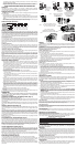
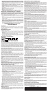
FIG. 1
1 HOUR CHARGER
CHARGEUR 1 HEURE
CARGADOR
DE 1 HORA
15 MIN
CHARGER
CHARGEUR 15
MINUTES
CARGADOR DE
15 MINUTOS
FIG. 2
RELEASE BUTTON
BOUTON DE
DÉGAGEMENT
BOTÓN DE DESTRABADO
FIG. 3
FIG. 4
FIG. 5
FIG. 6
TORQUE ADJUSTMENT COLLAR
COLLIER DE RÉGLAGE DE COUPLE
COLLAR DE AJUSTE DEL PAR
DUAL RANGE GEARING
ENGRENAGE À DOUBLE GAMME
ENGRANAJE DE DOS VELOCIDADES
FIG. 7
FIG. 8
DEPRESS FOR REVERSE
ENFONCER POUR LA
ROTATION ARRIÈRE
ADELANTE
DEPRESS FOR FORWARD
ENFONCER POUR LA
ROTATION AVANT
ATRÁS