


Mounting and Using Cutting
(Type 1) Wheels
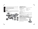
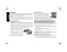
Cutting wheels include diamond wheels and abrasive discs. Abrasive
cutting wheels for metal and concrete use are available. Diamond
blades for concrete cutting can also be used.
WARNING: A closed, 2-sided cutting wheel guard is not included
with this tool but is re quired when using cutting wheels. Fail ure to
use proper flange and guard can re sult in injury resulting from wheel
breakage and wheel contact. See page 10 for more information.
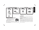
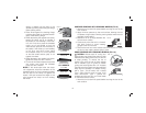
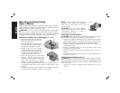
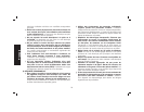
MOUNTING CLOSED (TYPE 1) GUARD (FIG. 16, 17, 18)
1. Open the guard latch (J). Align the
J
K
L
FIG. 16
lugs (K) on the guard with the slots
(L) on the gear case.
2. Push the guard down until the guard
lug engages and rotates freely in
the groove on the gear case hub.
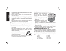
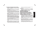
3. Rotate guard (G) into desired
working position. The guard body
should be positioned between the
spindle and the operator to provide
maximum operator protection.
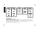
4. Close the guard latch to secure the
G
FIG. 17
guard on the gear case cover. You
should be unable to rotate the guard by
hand when the latch is in closed
position. If rotation is possible, tighten
the adjusting screw (M) with clamp lever in the closed position. Do
not operate grinder with a loose guard or clamp lever in open
position.
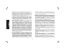
5. To remove the guard, open the guard latch, rotate the guard so
that the arrows are aligned and pull up on the guard.
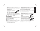
NOTE: If, after a period of time, the guard
M
FIG. 18
becomes loose, tighten the adjusting
screw (M) with the clamp lever in the
closed position.
CAUTION: Do not tighten adjusting
screw with clamp lever in open position.
Undetectable damage to guard or
mounting hub may result.
MOUNTING CUTTING WHEELS
CAUTION: Matching diameter threaded backing flange and clamp
nut (included with tool) must be used for cutting wheels.
1. Place the unthreaded backing flange on spindle with the raised
section (pilot) facing up. The raised section (pilot) on the backing
flange will be against the wheel when the wheel is installed.
2. Place the wheel on the backing flange, centering the wheel on the
raised section (pilot).
3. Install the threaded clamp nut with the raised section (pilot)
facing away from the wheel.
4. Depress the spindle lock button and tighten clamp nut with a
wrench.
5. To remove the wheel, grasp and turn while depressing the
spindle lock button.
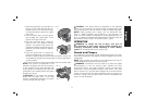
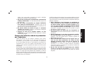
USING CUTTING WHEELS (FIG. 19)
WARNING: Do not use edge grinding/cutting wheels for surface
grinding applications because these wheels are not designed for side
pressures encountered with surface grinding. Wheel breakage and
injury may result.
1. Allow tool to reach full speed before touching tool to work
surface.
English
16