


12
English
Ripping
WARNING: Never touch the free end of the workpiece or a free piece that is cut off, while
the power is ON and/or the saw blade is rotating. Piece may contact the blade resulting in a
thrown workpiece and possible injury.
WARNING: A rip fence should ALWAYS be used for ripping operations to prevent loss of
control and personal injury. NEVER perform a ripping operation freehand. ALWAYS lock the
fence to the rail.
WARNING: When bevel ripping and whenever possible, place the fence on the side of the
blade so that the blade is tilted away from the fence and hands. Keep hands clear of the blade
and use a push stick to feed the workpiece if there is less than 6" (152 mm) between the fence
and the blade.
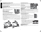
1. Lock the rip fence by pressing the rail lock lever down. Remove the miter gauge.
2. Raise the blade so it is about 1/8" (3.2 mm) higher than the top of the workpiece.
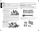
3. Hold the workpiece flat on the table and against the fence. Keep the workpiece about 1"
(25.4 mm) away from the blade.
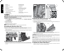
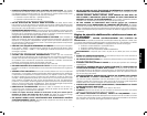
CAUTION: The workpiece must have
FIG. 33
a
straight edge against the fence and must
not be warped, twisted or bowed. Keep
both hands away from the blade and
away from the path of the blade. Refer to
proper hand position in Figure 33.
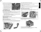
4. Turn the saw on and allow the blade to
come up to speed. Both hands can
be used in starting the cut. When there i s
approximately 12" (305 mm) left to
be ripped, use only one hand, with
your thumb pushing the material, your index and second finger holding the material down
and your other fingers hooked over the fence. Always keep your thumb along side your
first two fingers and near the fence.
5. Keeping the workpiece against the table and fence, slowly feed the workpiece rearward
all the way through the saw blade. Continue pushing the workpiece until it is clear of the
blade guard assembly and it falls off the rear of the table. Do not overload the motor.
6. Never try to pull the workpiece back with the blade turning. Turn the switch off, allow the
blade to stop, raise the anti-kickback teeth on each side of the riving knife if necessary and
slide the workpiece out.
7. When sawing a long piece of material or a panel, always use a work support. A sawhorse,
rollers, or out feed assembly provides adequate support for this purpose. The work
support must be at the same height as the saw table.
CAUTION: Never push or hold onto the free or cut off side of the workpiece.
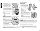
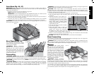
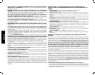
Ripping Small Pieces
It is unsafe to rip small pieces. It
FIG. 34
U
is not safe to put your hands
close to the blade. Instead, rip
a larger piece to obtain the
desired piece. When a small
width is to be ripped and the
hand cannot be safely put
between the blade and the rip
fence, use one or more push
sticks. A pattern is included at
the end of this manual to make
push sticks. A push stick (U) is included with this saw, attached to the rip fence. Use the push
stick(s) to hold the workpiece against the table and fence, and push the workpiece fully past
the blade. Refer to Figure 34.
NOTE: The table saw is equipped with a narrow ripping fence that also supports work that
extends beyond the saw table. Refer to Work Support Extension/Narrow Ripping Fence
under Rip Fence Operation.
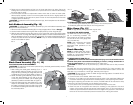
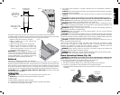
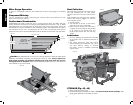
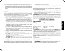
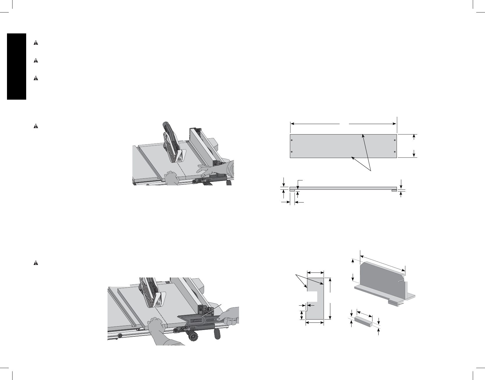
Narrow Rip Auxiliary Fence (Fig. 35–37)
The narrow rip auxiliary fence should be used for a rip measuring 2" (51mm) or narrower. This
fence will allow the guard to remain on the saw when completing narrow ripping. This fence will
provide ample space for proper use of a push block (A12, Refer to Push Block).
1. Follow the diagram in Figure 35 to construct the narrow rip auxiliary fence (A13, Fig. 37).
NOTE: A11 should be cut to fit the length of the saw table top and sides (A14) must be
parallel.
3/8"
(9.5 mm)
1"
(25 mm)
1/2"
(12.7 mm)
FIG. 35
A14
A11
4-3/4"
(121 mm)
3/8"
(9.5mm)
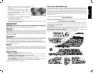
2. After the narrow rip auxiliary fence is constructed, slip it over the saw table top and place
it flush to the fence as shown in Figure 37.
3. Feed the workpiece through until the edge of the material reaches the front edge of the
saw table top.
4. Continue feeding the material using the push block (A12) until the cut is complete.
12
"
(305mm)
A12
A15
FIG. 36
A16
2-1/2" (64mm)
5"
(127 mm)
1/2"
(12.7 mm)
4-3/4"
(121 mm)
12"
(305 mm)
1/2"
(12.7 mm)
5-1/4"
(133 mm)
2-1/2"
(64 mm)
1/2"
(12.7 mm)