


13
English
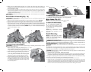
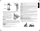
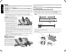
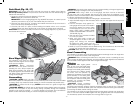
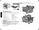
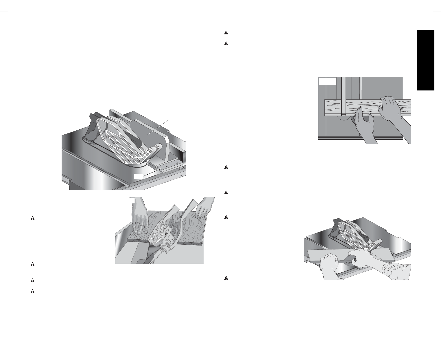
Push Block (Fig. 36, 37)
IMPORTANT: Only use the push block (A12) with the narrow rip auxiliary fence. Refer to
Narrow Rip Auxiliary Fence. The push block should be used once the material being cut
reaches the saw table top.
1. Construct a push block using the diagram in Figure 36.
NOTE: Edges (A15) must be the same size.
IMPORTANT: The over hanging edge (A16, Fig. 36) MUST be square. An uneven lip could
cause the push block to slip or push the material away from the fence.
2. Place the push block (A12, Fig. 37) behind the material and ensure the lip of the block is
flush to the narrow rip auxiliary fence (A13).
3. Once the push block is in place, continue feeding the material until the cut is complete
making sure the push block remains flush to the narrow rip auxiliary fence at all times.
IMPORTANT: The narrow rip auxiliary fence and the over hanging edge (A16, Fig. 36) should
both be the same thickness.
FIG. 37
A12
A13
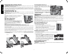
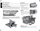
Bevel Ripping (Fig. 38)
This operation is the same as ripping
FIG. 38
except the bevel angle is set to an angle
other than zero degrees.
WARNING: Before connecting
the table saw to the power source or
operating the saw, always inspect the
blade guard assembly and riving knife
for proper alignment and clearance with
saw blade. Check alignment after each
change of bevel angle.
Crosscutting
WARNING: NEVER touch the free
end of the workpiece or a free piece that is cut off, while the power is ON and/or the saw blade
is rotating. Piece may contact the blade resulting in a thrown workpiece and possible injury.
WARNING: To reduce the risk of injury, NEVER use the fence as a guide or length stop
when crosscutting.
WARNING: NEVER use a length stop on the free end of the workpiece when crosscutting.
In short, the cut-off piece in any thru sawing (cutting completely through the workpiece)
operation must never be confined — it must be allowed to move away from saw blade to
prevent contact with blade resulting in a thrown workpiece and possibly injury.
WARNING: Use caution when starting the cut to prevent binding of the guard against the
workpiece resulting in damage to saw and possible injury.
CAUTION: When using a block as a cut-off gauge, the block must be at least 3/4"
(19 mm) thick and is very important that the rear end of the block be positioned so the
workpiece is clear of the block before it enters the blade to prevent contact with blade resulting
in a thrown workpiece and possibly injury.
1. Remove the rip fence and place the miter gauge in the desired slot.
2. Adjust the blade height so that the blade is about 1/8" (3.2 mm) higher than the top of the
workpiece.
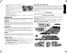
3. Hold the workpiece firmly against the
FIG. 39
miter gauge with the path of the blade in
line with the desired cut location. Keep
the workpiece an inch or so in front of the
blade. KEEP BOTH HANDS AWAY
FROM THE BLADE AND THE PATH OF
THE BLADE (Fig. 39).
4. Start the saw motor and allow the blade
to come up to speed.
5. While using both hands to keep the
workpiece against the face of the miter
gauge, and holding the workpiece
flat against the table, slowly push the
workpiece through the blade. Refer to Figure 38.
6. Never try to pull the workpiece with the blade turning. Turn the switch off, allow the blade
to stop, and carefully slide the workpiece out.
CAUTION: Never touch or hold onto the free or cut off end of the workpiece.
Bevel Crosscutting
This operation is the same as crosscutting except that the bevel angle is set to an angle other
than 0°. For proper hand position, refer to Figure38.
WARNING: Before connecting the table saw to the power source or operating the saw,
always inspect the blade guard assembly and riving knife for proper alignment and clearance
with saw blade. Check alignment after each change of bevel angle.
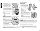
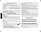
Mitering
WARNING: Miter angles greater
FIG. 40
than 45˚ may force the blade guard
assembly into the saw blade causing
damage to the blade guard assembly
and personal injury. Before starting
the motor, test the operation by
feeding the workpiece into the blade
guard assembly. If the blade guard
assembly contacts the blade, place
the workpiece under the blade guard
assembly, not touching the blade,
before starting the motor.
CAUTION: Certain workpiece
shapes, such as molding may not lift
the blade guard assembly properly. Feed the workpiece slowly to start the cut. If the blade
guard assembly contacts the blade, place the workpiece under the blade guard assembly,
not touching the blade, before starting the motor.
This operation is the same as crosscutting except the miter gauge is locked at an angle other
than 0°. Hold the workpiece FIRMLY against the miter gauge and feed the workpiece slowly
into the blade (to prevent the workpiece from moving). Refer to Figure 40.