


7
English
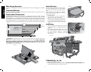
2. Rotate cam counterclockwise until the front of throat plate drops into place. Secure by
rotating cam lock knob (CC) clockwise 1/4 turn (when cam lock is under the table holding
the throat plate in place).
3. The throat plate includes four adjustment screws which raise or lower the throat plate.
When properly adjusted, the front of the throat plate should be flush or slightly below the
surface of the table top and secured in place. The rear of the throat plate should be flush
or slightly above the table top.
WARNING: To reduce the risk of serious personal injury, the throat plate must be locked in
place at all times.
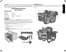
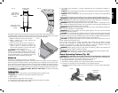
Anti-Kickback Assembly (Fig. 10)
WARNING: To reduce the risk of serious personal injury, the anti-kickback assembly must
be in place for all possible cuts.
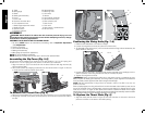
1. Remove the anti-kickback assembly (Q) from the storage position. Refer to Storage.
2. Locate the anti-kickback mounting hole and slot (EE) at the top of the riving knife (FF).
3. Slide the anti-kickback housing along the top of the riving knife until the stem (GG) locates
the slot above the mounting hole. Depress the stem (GG) on the anti-kickback assembly to
allow the assembly to drop into the hole (EE). Push down on the anti-kickback assembly until
it snaps into place and locks the assembly. NOTE: Pull up on the anti-kickback assembly to
ensure it has locked into place.
GG
Q
FF
FIG. 10
EE
Q
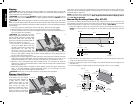
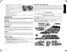
Blade Guard Assembly (Fig. 11, 12)
TO ATTACH BLADE GUARD ASSEMBLY
WARNING: To reduce the risk of serious personal injury, the blade guard assembly must be
in place for all possible cuts.
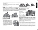
1. While holding the blade guard assembly (D) in a
HH
D
FIG. 11
II
vertical position slide the locating pin (HH) into the
riving knife slot (II) centering the riving knife within the
v-shaped notch in the top guard. Refer to Figure11.
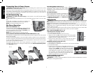
2. Rotate the blade guard assembly toward the front
of the saw while keeping the pin (HH) at the top
of the riving knife slot. Rotate until the blade guard
assembly is parallel to the table. Refer to Figure12.
3. Press the blade guard lock lever (WW) down until it
snaps into the locked position. Check to make sure
the guard is locked onto the riving knife. If the guard
is not locked the blade guard lock lever will flip up to
the unlocked position.
WW
FIG. 12 FIG. 12A FIG. 12B
WW
TO REMOVE BLADE GUARD ASSEMBLY
1. Lift the blade guard assembly lock lever (WW) to the unlocked position.
2. Rotate the guard back and slide pin from riving knife slot.
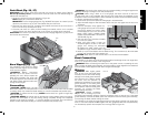
Miter Gauge (Fig. 13)
NOTE: A large auxiliary miter gauge face may be used.
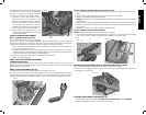
TO ATTACH THE MITER GAUGE
FIG. 13
JJ
B
The DWE7480 includes a miter gauge
(B) for crosscutting materials. The
miter gauge can be used by inserting
into one of the two miter gauge slots
(JJ) in the table top.
NOTE: See crosscutting and bevel
crosscutting instructions before
performing these operations on the
table saw.
Bench Mounting
NOTE: A portable table saw stand is
designed for use with this saw and is
available at a local D
EWALT dealer or
service center at extra cost.
TO BENCH MOUNT SAW (FIG. 3)
WARNING: To reduce the risk of serious personal injury, turn unit off and disconnect
machine from power source before attempting to move it, change accessories or
make any adjustments. An accidental start-up can cause injury.
CAUTION: To reduce the risk of personal injury, make sure table saw is firmly mounted
before use.
The table saw must be mounted firmly. Four mounting holes (N, Fig. 3) are provided in the
metal frame for mounting. We strongly recommend that these holes be used to anchor the
table saw to your workbench or other rigid, stationary work support.
CAUTION: Ensure that the surface is stable enough that large pieces of material will not
cause it to tip over during use.
1. Center the saw on the desired, stable work surface.
2. Drive four 3-1/2" (88.9 mm) long screws through the holes in the metal frame. Make sure
the screws extend through the frame and securely attach to the supporting work surface.
If marring the supporting work surface is a concern, the DWE7480 can be mounted to scrap
wood which can then be clamped onto the desired work surface.
1. Cut a piece of 3/4" (19 mm) plywood to fit beneath the footprint of the saw.
2. Screw the saw to the plywood and clamp the overhang of the plywood to the work
surface. If the screws protrude through the plywood base, set it on two scrap pieces of
material of equal thickness and attach them to the edges of the plywood to hold the saw
further off of the work surface and prevent the screws from marring the surface.