


8
English
Connecting Saw to Power Source
WARNING: To reduce the risk of injury, before connecting saw to power source, make
sure the switch is in the OFF position.
Be sure your power supply agrees with the nameplate marking. AC Only means that your saw
will operate on alternating current only. A voltage decrease of 10 percent or more will cause
a loss of power and overheating. All D
EWALT tools are factory tested. If this tool does not
operate, check the power supply.
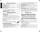
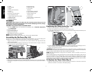
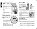
On-Off Switch (Fig. 14)
WARNING: To reduce the risk of injury, be sure switch is in the OFF position before
plugging machine in.
Lift the ON/OFF switch (K) paddle up to turn your saw ON and push it down to turn your saw
OFF.
A hole (KK) is provided in the switch for insertion of a
FIG. 14
K
KK
padlock with a removable shank to lock the saw off.
NOTE: A conventional padlock will not fit.
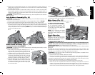
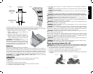
Rip Fence Operation
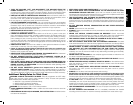
RAIL LOCK LEVER (FIG. 15)
The rail lock lever (W) locks the fence in place preventing
movement during cutting. To lock the rail lever, push it
down and toward the rear of the saw. To unlock, pull it
up and toward the front of the saw.
NOTE: When ripping, always lock the rail lock lever.
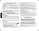
WORK SUPPORT EXTENSION/NARROW RIPPING FENCE (FIG. 15, 16)
The table saw is equipped with a narrow ripping fence that also supports work that extends
beyond the saw table.
To use the narrow ripping fence in the work support position, rotate it from its stored position
as shown in Figure 16, and slide the pins into the lower sets of slots on both ends of the fence.
To use the narrow ripping fence in the narrow ripping position, snap the pins into the upper
sets of slots on both ends of the fence.
This feature will allow 2" (51 mm) of extra clearance to the blade. If more clearance is
necessary, follow directions for making an auxiliary fence under Narrow Rip Auxiliary Fence
in the Operation section.
FIG. 15
FIG. 16
W
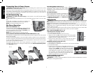
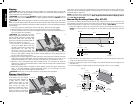
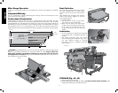
FINE ADJUSTMENT KNOB (FIG. 17)
The fine adjustment knob (H) allows smaller
FIG. 17
NN
H
adjustments when setting the fence. Before
adjusting, be sure the rail lock lever is in its up or
unlocked, position.
RIP SCALE POINTER
The rip scale pointer will need to be adjusted for
proper performance of the rip fence if the user
switches between thick and thin kerf blades. Refer
to Adjusting the Rip Scale under Adjustments
for alignment instructions.
Adjustments
WARNING: To reduce the risk of injury, turn unit off and disconnect machine from
power source before installing and removing accessories, before adjusting or changing set-
ups or when making repairs. An accidental start-up can cause injury.
NOTE: Your saw is fully and accurately adjusted at the factory at the time of manufacture. If
readjustment due to shipping and handling or any other reason is required, follow the steps
below to adjust your saw.
Once made, these adjustments should remain accurate. Take a little time now to follow these
directions carefully to maintain the accuracy of which your saw is capable.
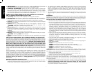
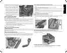
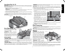
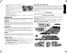
RAIL LOCK ADJUSTMENT (FIG. 3, 18)
FIG. 18
LL
MM
(Tightening Fence Clamping System)
1. Lock the rail lock lever (W).
2. On the underside of the saw, loosen the nut (LL).
3. Tighten the hex rod (MM) until the spring on the locking system
is compressed creating the desired tension on the rail lock lever.
Retighten the jam nut against the hex rod.
4. Check that the fence does not move when the lock lever is
engaged. If the fence is still loose, tighten the spring further.
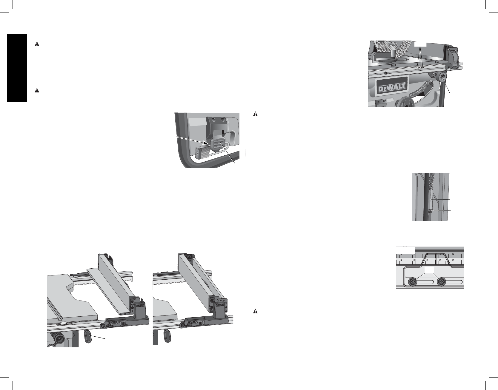
ADJUSTING THE RIP SCALE (FIG. 3, 19)
1. Unlock the rail lock lever (W).
2. Set the blade at 0° bevel and move the fence in until it touches the blade.
3. Lock the rail lock lever.
4. Loosen the rip scale indicator screws (NN) and set the rip
FIG. 19
NN
scale indicator to read zero (0). Retighten the rip scale
indicator screws. NOTE: The yellow rip scale (top) reads
correctly only when the fence is mounted on the right side
of the blade and is in position 1 (for 0 to 20" ripping, not the
24" rip position). The white scale (bottom) reads correctly
only when the fence is mounted on the right side of the
blade and in position 2 (for 4" to 24" ripping).
BLADE ALIGNMENT ADJUSTMENT
(Blade Parallel to Miter Slot)
WARNING: Cut Hazard. Check the blade at 0˚ and 45˚ to make sure blade does not hit the
throat plate, causing personal injury.