


12
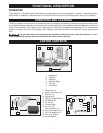
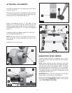
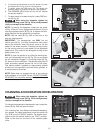
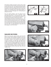
4. To stop the spindle without turning the power off, press
the stop button (C) Fig. 22 on the control panel.
5. To restart, press the FWD button (B). The spindle will
gradually return to the speed at which it was stopped.
6. The REVERSE (REV) button (D) Fig. 22 will reverse
the spindle rotation.
7. To return back to forward direction, press FWD but-
ton (E) Fig. 22.
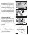
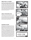
When using the faceplate, tighten the
faceplate locking screw (A) Fig. 23 to avoid personal
injury or damage to the machine.
NOTE: To remove the faceplate, loosen the set screw
(A) Fig. 23 two full turns. Engage the spindle lock (C) and
use the supplied wrench (B) Fig. 24 to loosen the face-
plate. Remove the face plate from the spindle.
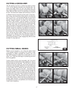
NOTE: Use the chart (B) Fig. 25A on the front of the
door for safe operation.
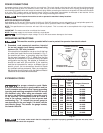
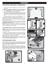
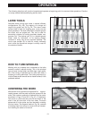
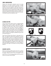
IMPORTANT: For emergencies, use ONLY the red
switch cover (A) Fig. 19 to stop the machine. Also, when
leaving the machine, lower the switch cover to cut the
power to the whole machine. Pressing the stop button
on the control panel only cuts power to the adjustable
speed drive. This control is still energized as long as the
power switch is on.
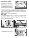
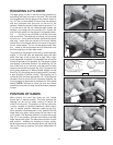
NOTE: To lock the spindle or to utilize the indexing fea-
ture, pull the spindle lock pin (A) Fig. 25 out and rotate
the pin clockwise. Engage it in the pulley holes (B) Fig.
25, some of which are shown. The spindle pulley has 24
holes accurately spaced around the rim of the pulley.
This feature makes it possible to make evenly spaced
divisions on turnings which could be fluted, grooved, or
to mark places to be drilled.
NOTE: Delta does not suggest the use of any optional
brake systems on the lathe. Further, DO NOT CHANGE
OR ADJUST the controller settings that have been pre-
set at the factory.
B
A
B
A
Fig. 22
Fig. 23
Fig. 24
Fig. 25
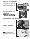
CHANGING ACCELERATION/DECELERATION
When using the faceplate, tighten the
faceplate locking screw (A) Fig. 23 to avoid personal
injury or damage to the machine.
To change the acceleration/deceleration rate, loosen the
screw (A) Fig. 25A and open the door.
This machine has two different acceleration/decelera-
tion speeds. For larger workpieces, move the switch (A)
Fig. 25 B up to the “SLOW” position. For smaller work-
pieces, move the switch down to the “FAST” position.
Refer to the chart on the front of the variable speed
drive.
Fig. 25A
Fig. 25B
A
A
B
C
C
B
A
D
E