


9
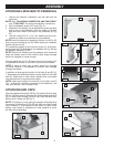
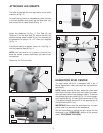
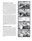
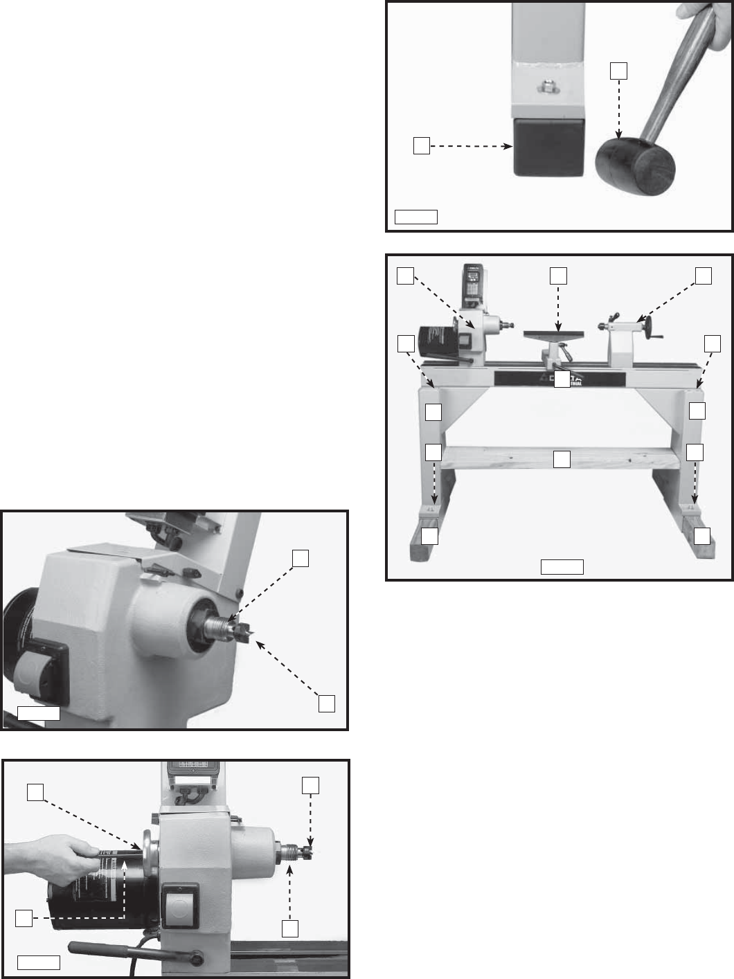
ATTACHING LEG INSERTS
The lathe is supplied with four leg inserts, one of which
is shown (A) Fig. 10.
To attach the leg inserts to the pedestals, place one side
in the hole provided and gently tap the other side, top,
and bottom with a rubber mallet (B) Fig. 10.
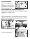
If additional stability is desired, insert a 4 x 4 (A) Fig. 11
into the pedestal base (B) Fig. 11.
NOTE: You may have to cut a groove in the 4x4”s to
allow the lumber to pass underneath the head of the
carriage bolt.
Fasten the 4 x 4’s to the floor.
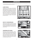
HEADSTOCK SPUR CENTER
The spur center (A) Fig.12 is equipped with a No. 2
Morse Taper shank. Insert this shank into the headstock
spindle (B).
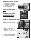
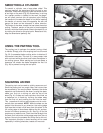
NOTE: Before inserting the spur center (A), clean both
the shank of the spur center and the inside of the head-
stock spindle to remove any grease or debris. To remove
the tapered shank spur center (A) Fig. 13 from the head-
stock spindle (B) Fig. 13, insert the knockout bar (C) Fig.
13 (supplied) through the hole (D) in the opposite end of
the spindle and push it out.
IMPORTANT: Never drive the workpiece into the spur
center when it is mounted on the headstock.
See the instructions on setting the spur center into the
workpiece in the “OPERATION“ section of this manual
under “CENTERING THE WORK.”
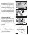
Attach the Headstock (A) Fig. 11, Tool Rest (E), and
Tailstock (F) to the lathe bed (G). Notice the tool and
centers storage areas located at (H), and brackets on
the pedestals to accept a 2 x 12” shelf (not supplied)
(J) Fig. 11.
A
B
A
C
C
B
B
H
J
H
A
G
F
A E
B
A
D
C
A
B
Fig. 10
Fig. 11
Fig. 12
Fig. 13