13
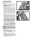
Fig. 20
Fig. 19
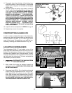
Fig. 21
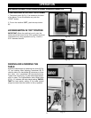
TABLE ROLLERS
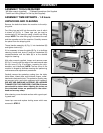
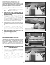
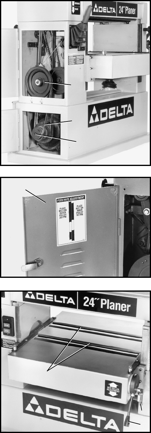
Your planer is supplied with two table rollers (A) Fig. 21,
which aid in feeding the stock by reducing friction be-
tween the stock and the table and rotate as the stock
is fed through the planer.
1. To raise the table rollers, loosen locking lever (B) Fig.
21, and pull control lever (C) upward to the desired
height setting.
2. To lower the table rollers, loosen locking lever (B) Fig.
21, and push control lever (C) downward to the
desired height setting.
3. After adjusting height of the table rollers, tighten
locking lever (B) Fig. 21.
C
F
E
G
A
B
C
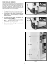
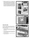
6. Reposition drive belt (E) Fig. 19, on pulleys (F) and
(G). When belt (E) Fig. 19, is on the smallest step of
motor pulley (G) and the largest step of the gear box
pulley (F), the feed roller speed will be 20 feet per
minute. When belt (E) Fig. 19, is on the largest step
of the motor pulley (G) and the smallest step of gear
box pulley (F), the feed roller speed will be 30 feet
per minute. A feed rate adjustment chart is located
on the back of panel (C) Fig. 20, for quick reference.


