16
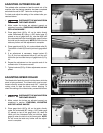
1. DISCONNECT THE MACHINE FROM
THE POWER SOURCE.
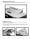
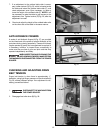
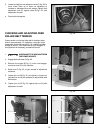
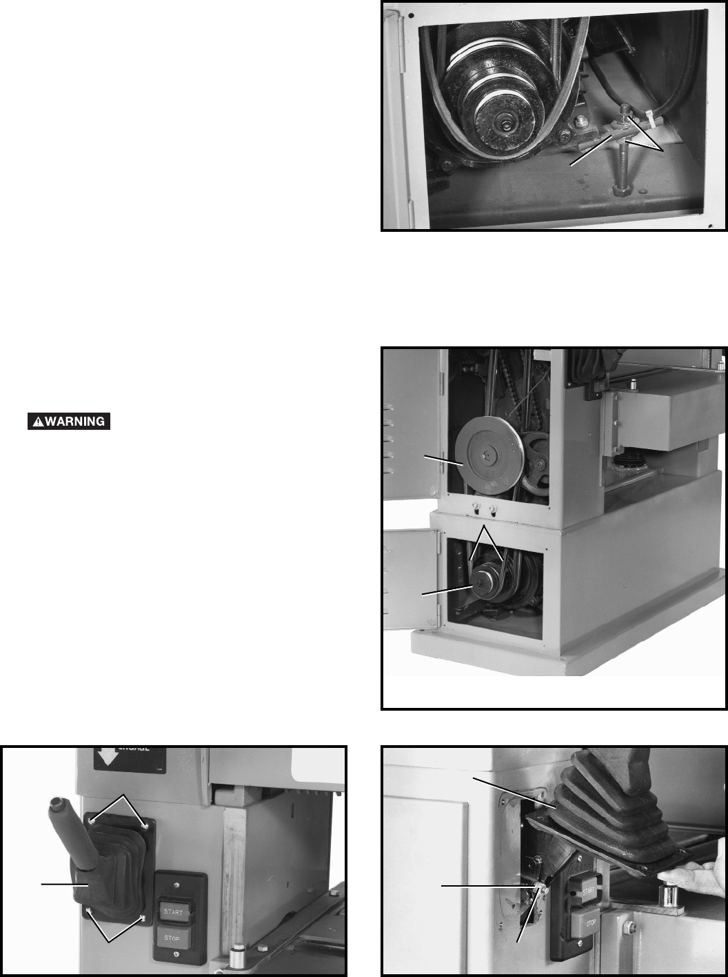
2. Engage feed roller lever (D) Fig. 30.
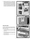
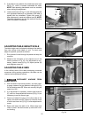
3. Remove four screws (E) Fig. 31, which hold engage-
ment lever boot (F) to the machine.
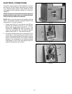
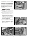
4. Raise boot (F) Fig. 32, to gain access to adjustment
hardware.
5. Loosen jam nut (G) Fig. 32, and tighten or loosen ad-
justment hex nut (H) as necessary to adjust feed roller
belt tension.
6. Tighten jam nut (G) Fig. 32, against hex nut (H) after
adjustment is made.
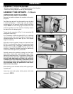
CHECKING AND ADJUSTING FEED
ROLLER BELT TENSION
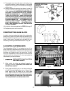
Proper tension on the feed roller belt is obtained when
there is approximately 1/2 deflection, using light finger
pressure on feed roller belt (A) Fig. 30. midway between
pulleys (B) and (C), with feed roller lever (D) engaged. If
an adjustment is necessary, proceed as follows:
Fig. 31
Fig. 32
E
F
E
F
H
G
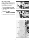
Fig. 29
D
C
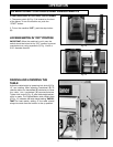
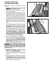
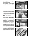
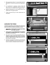
3. Loosen and tighten two adjustment nuts (C) Fig. 29, to
move motor plate up or down as necessary to
increase or decrease drive belt tension.Tighten both
adjustment nuts (C) against plate (D) Fig. 29, after
adjustment is made.
4. Close both side panels.
Fig. 30
B
A
C


