9
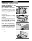
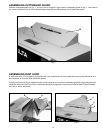
ASSEMBLING CUTTERHEAD GUARD
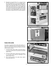
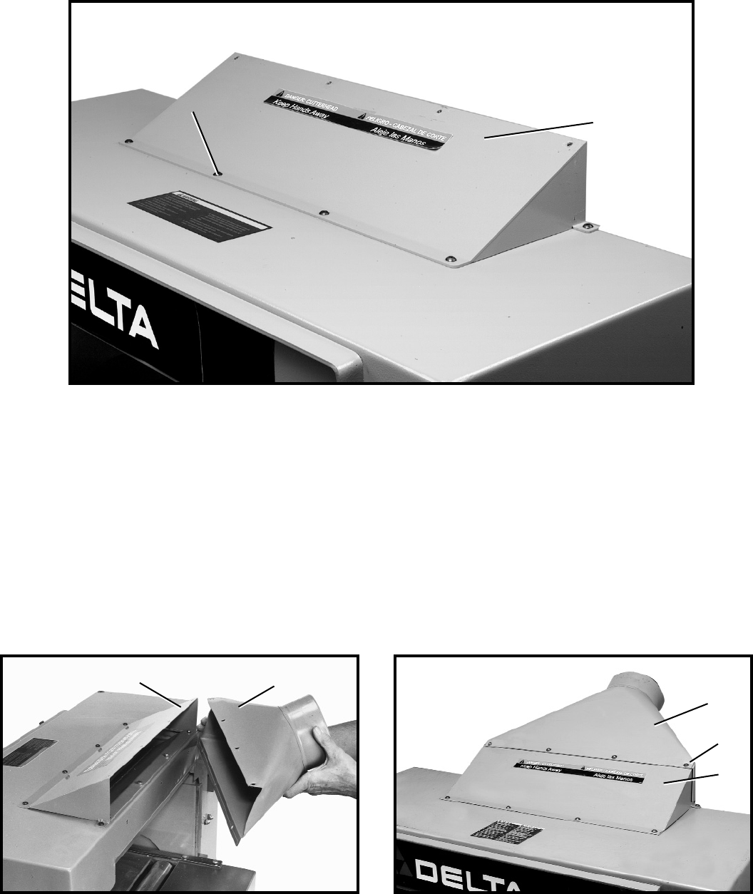
Position cutterhead guard (A) Fig. 7, on top cover of machine. Align holes in cutterhead guard (A) Fig. 7, with holes in
top cover and fasten with six 12mm button head screws (B) and flat washers, five of which are shown.
Fig. 8 Fig. 9
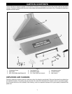
ASSEMBLING DUST HOOD
A dust hood with a 5-inchopening is supplied with your machine and is to be used when connecting the planer to a
dust collector or a central dust collection system.
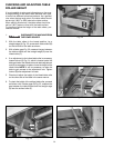
Position dust hood (A) Fig. 8, against the rear of the machine and on top of cutterhead guard (B). Align the holes and
fasten the dust hood (A) Fig. 9, to the cutterhead guard (B) using seven 12mm button head screws (C) and flat wash-
ers, four of which are shown.
A
B
Fig. 7
B
C
A
B
A


