21
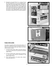
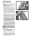
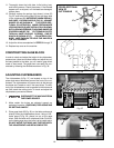
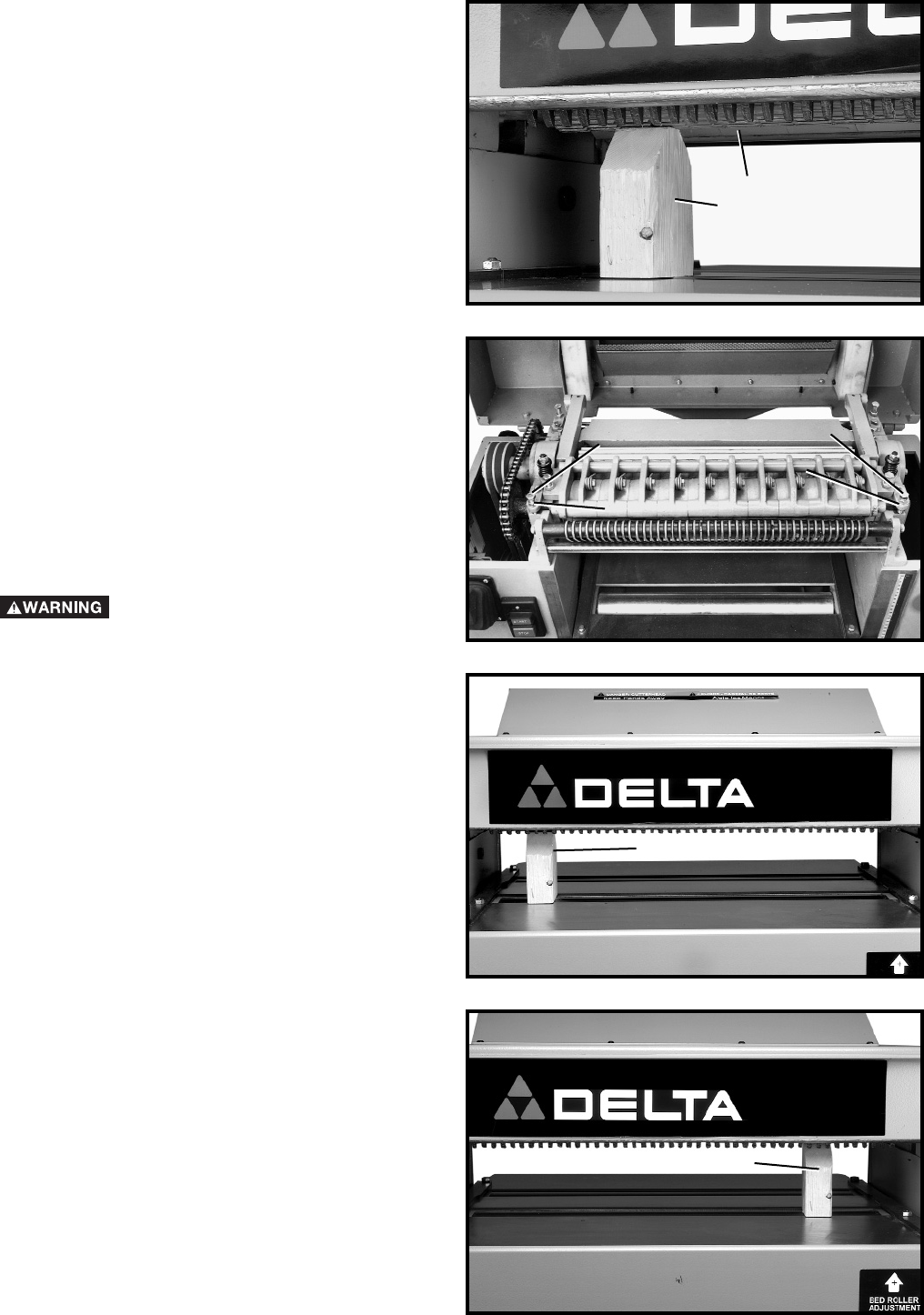
Fig. 48
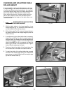
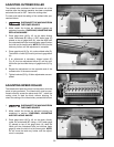
Fig. 50
LEVELING THE TABLE
The table is set parallel to the cutterhead at the factory and
no further adjustment should be necessary. To check if the
table is level with the cutterhead, proceed as follows:
1. DISCONNECT THE MACHINE FROM
THE POWER SOURCE.
2. Check to see if the cutterhead knives are set correctly
as explained in section “CHECKING, ADJUSTING
AND REPLACING KNIVES.”
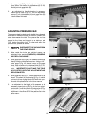
3. Then check to see if the table is set parallel to the cut-
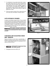
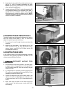
terhead by placing gage block (A) Fig. 49, directly
under the cutterhead on the left hand side of the table
as shown. Raise the table until gage block (A) Fig. 49,
just touches the cutterhead.
4. Carefully move gage block (A) Fig.50, to the right hand
side of the table directly under the cutterhead. The dis-
tance from table to cutterhead should be identical.
Fig. 49
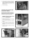
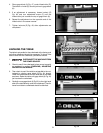
4. Place gage block (A) Fig. 47, under infeed roller (D).
The bottom of roller (D) should just touch gage block
(A).
5. If an adjustment is necessary, loosen locknut (E)
Fig. 48, and turn adjustment screw (F) until the
infeed roller just touches the top of gage block (A).
6. Repeat the adjustment on the opposite end of the
infeed roller in the same manner.
7. Tighten locknuts (E) Fig. 48, after adjustments are
completed.
Fig. 47
D
A
E
F
E
F
A
A


