


- 4 -
44104
D
U
K
A
N
E
A
A
p
p
p
p
l
l
i
i
c
c
a
a
t
t
i
i
o
o
n
n
N
N
o
o
t
t
e
e
AN200
Rev 01
© Dukane Corporation 2003. All rights reserved.
Dukane Corporation
2900 Dukane Drive Saint Charles, IL 60174 USA
Phone (630) 797-4900 FAX (630) 797-4949
http://www.dukane.com/us
Intelligent Assembly Solutions
4
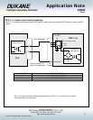
System Input Signal Descriptions:
Isolated Operate Input - ( Pin 3 ) This system input signal receives the cycle initiation signal from automation. The
minimum duration for the activation of this input is 50 mS. The maximum duration of this input is
determined by the duration of the weld cycle. This input should be deactivated before the end of
the weld cycle to avoid an error condition. This system input can be reconfigured to
accommodate sourced (PNP) and sinking (NPN) signals as described in the SH707 configuration
section of this document. Please refer to the DPC manual for details on the activation and use of
the Operate (cycle initiate) feature.
Note: Reconfiguring the jumper of the SH901 jumper block on the 110-3938 press PCB will
configure the system to activate both the press and the ultrasound simultaneously at the top of
stroke position of the press.
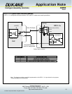
Isolated Press Control Input - ( Pin 5 ) This system input receives a signal from automation that activates the Dukane
pneumatic press to the down position. The press will remain in the down position until this system
input is deactivated. This system input can be reconfigured to accommodate sourced (PNP) and
sinking (NPN) signals as described in the SH707 configuration section of this document. SH901
of the 110-3938 press board must also be reconfigured to the “Auto Control” position to activate
this system input. Please refer to the DPC manual for details on the activation and use of the
Press Control feature.
Operate Input - ( Pin 8 ) This system input signal receives the cycle initiation signal from automation. The
minimum duration for the activation of this input is 50 mS. The maximum duration of this input is
determined by the duration of the weld cycle. This input should be deactivated before the end of
the weld cycle to avoid an error condition. The system input can only accommodate a non-
isolated sinking (NPN) signal for activation.
Note: Reconfiguring the jumper of the SH901 jumper block on the 110-3938 press PCB will
configure the system to activate both the press and the ultrasound simultaneously at the top of
stroke position of the press.
Isolated Automation Stop/End of Weld - ( Pin 9 ) This system input receives a signal from automation that will stop the
processing of portions of the welding cycle. The default functionality for this input is to end the
weld portion of the DPC cycle when the system input is activated. This input can be reconfigured
to Automation Stop which will stop the processing of all portions of the DPC cycle. Configuration
of this feature is described in the SH704 jumper configuration section of this document.
Hand Probe Press Inhibit - ( Pin 11 ) This system input receives a signal from a Dukane hand probe that disables all
press functionality.
MPC Probe / Setup Bit 1, 2, and 3 - ( Pins 12, 13, 14 ) These system inputs receive a Binary code from automation that
is used to select a DPC setup and a DPC probe to be used for the next welding cycle. Please
refer to the DPC manual or application AN203 for details on the activation and use of the MPC or
Remote Setup Select (DPCII+ only) features.
Front Panel Control Lock - ( Pin 15 ) This system input receives a signal from automation that disables the DPC test
switch as well as the key pad for the DPC controller (DPC II+ only).
(MPC Feature Optional)