


- 5 -
55105
D
U
K
A
N
E
A
A
p
p
p
p
l
l
i
i
c
c
a
a
t
t
i
i
o
o
n
n
N
N
o
o
t
t
e
e
AN200
Rev 01
© Dukane Corporation 2003. All rights reserved.
Dukane Corporation
2900 Dukane Drive Saint Charles, IL 60174 USA
Phone (630) 797-4900 FAX (630) 797-4949
http://www.dukane.com/us
Intelligent Assembly Solutions
5
Internal DPC Jumper Block Configuration Options
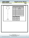
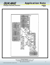
The DPC II / II+ provides four internal jumpers that allow the user to configure the system inputs for compatibility with the
users equipment. Three of the configurable jumpers are located on the DPC II / II+ 110-3606 system interface board
which is located in bottom of the DPC near the rear panel. The 110-3606 system interface board can be identified as the
board connected to the System Input and System Output connectors which extend from the back panel of the DPC II / II+
chassis. The fourth configurable jumper is located on the 110-3937 press control board. The press control board can be
identified as the board connected to the press control cable which is connected to the DPC press.
Warning: The DPC chassis cover should not be removed until the DPC power cord has been removed from the AC
voltage supply. After removing the DPC power cord from the AC voltage supply, the DPC requires fifteen minutes to
discharge to safe levels. Do not remove the DPC cover until the DPC has discharged to safe levels. Avoid contact with
all internal DPC components that are not specified within the jumper configuration procedure below. Failure to comply
with these requirements can result in serious personal injury and damage to the DPC welding system.
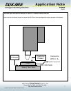
Automation Cycle Stop / End of Weld Configuration
(Associated with pin 9)
Jumper Block – SH704
JU713 – Normally OFF (Factory Default )
JU714 – Normally ON
JU715 – Automation Stop Fault
JU716 – Automation End of Weld (Factory Default)
Note: There will be two jumpers instaled in SH704.
Switch Debounce Filter Delay for System Inputs
(Associated with pins 3 and 8)
Jumper Block – SH705
JU717 – No Time Delay (used for solid state switches)
JU718 – 1 msec
JU719 – 10 msec (Factory Default)
JU720 – 22 msec
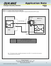
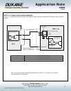
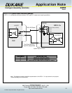
System Input Signal Type Configuration
(Associated with pins 3, 5, and 9)
Jumper Block – SH707
JU724 – Non Isolated Sink (Factory Default) Dry contact between input and DPC ground.
JU725 – Non Isolated Source Dry contact between input and +22VDC.
JU726 – Isolated Source Input can be either sinking (NPN) or sourcing (PNP). A signal of
5 to 24 VDC is required at the isolated input pin. The current is
internally limited to 12.5mA.