


- 9 -
99109
D
U
K
A
N
E
A
A
p
p
p
p
l
l
i
i
c
c
a
a
t
t
i
i
o
o
n
n
N
N
o
o
t
t
e
e
AN200
Rev 01
© Dukane Corporation 2003. All rights reserved.
Dukane Corporation
2900 Dukane Drive Saint Charles, IL 60174 USA
Phone (630) 797-4900 FAX (630) 797-4949
http://www.dukane.com/us
Intelligent Assembly Solutions
9
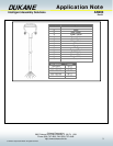
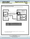
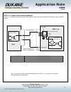
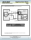
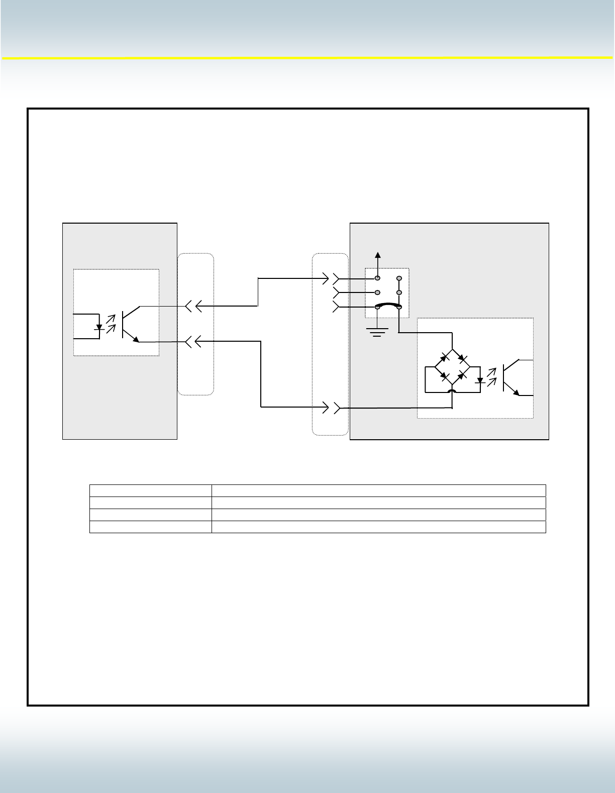
DPC II / II+ System Input Interface Example:
(DPC II / II+ configured to accommodate a PNP type PLC output card that utilizes the DPC power to source the DPC
inputs).
Bi-directional
Input Device
+22 VDC
DPC II / II+
J701
Output Device
PLC
4
200-1203 Cable
JU724 (Factory Default)
JU726
JU725
1
2
PIN NUMBER PIN DESCRIPTION
3 ISOLATED OPERATE INPUT
5 ISOLATED PRESS CONTROL
9 ISOLATED AUTOMATION STOP/END OF WELD
Note: This diagram provides a simplified representation of the DPC II / II+ input device for the purpose
of demonstrating circuit functionality.
See Chart Below for
Input Pin assignments