


- 2 -
22102
D
U
K
A
N
E
A
A
p
p
p
p
l
l
i
i
c
c
a
a
t
t
i
i
o
o
n
n
N
N
o
o
t
t
e
e
AN400
© Dukane Corporation 2004. All rights reserved.
Dukane Corporation
2900 Dukane Drive Saint Charles, IL 60174 USA
Phone (630) 797-4900 FAX (630) 797-4949
http://www.dukane.com/us
Intelligent Assembly Solutions
2
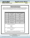
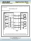
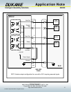
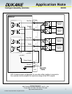
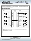
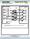
J602 User Interface Connector
The J602 User Interface connector is the primary communications link between the DPC IV and user automation
equipment. This connector provides status signals that can be used to monitor DPC weld data analysis results as well
as timing issues related to the processing of the weld sequence. It also provides the automation with dedicated
communication lines that allows the automation to control the beginning and the end of a welding sequence.
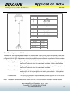
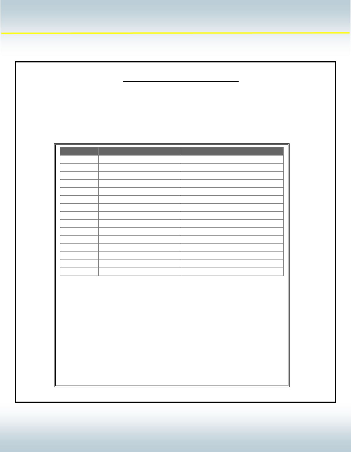
Pin Number DPC Signal Name DPC Signal Type
1 Power Su
pp
l
y
+22 VDC
(
0.5 am
p
max
)
2 Groun
d
Power Su
pp
l
y
Retur
n
3 Bad Part Out
p
ut
4 Sus
p
ect Part
(
see note #2
)
Out
p
ut
5 Good Part Out
p
ut
6 Read
y
(
see note #1
)
Out
p
ut
7 Isolated Out
p
ut Common Common Pin for Out
p
ut Si
g
nals
8 Automation In
p
ut In
p
ut
9 Automation Sto
p
N/C In
p
ut
10 Automation Sto
p
N/O In
p
ut
11 Hand Probe Press Inhibit In
p
ut
12 In
p
ut Common Common Pin for In
p
ut Si
g
nals
13 Groun
d
Power Su
pp
l
y
Retur
n
14
15 Ground Detect In
p
ut
Note #1: This input can be reconfigured in the DPC IV menu choices to activate during
the following weld sequence event:
In Cycle
Sonics On
In Hold
Note #2: This input can be reconfigured in the DPC IV menu choices to activate during
the following weld sequence event:
Network Active
Sonics On
Note: Please refer to the Hardware Setup section of the DPC IV manual for details on
reconfiguring pin 4 or pin 6 to the required status output signal.