


- 4 -
44104
D
U
K
A
N
E
A
A
p
p
p
p
l
l
i
i
c
c
a
a
t
t
i
i
o
o
n
n
N
N
o
o
t
t
e
e
AN400
© Dukane Corporation 2004. All rights reserved.
Dukane Corporation
2900 Dukane Drive Saint Charles, IL 60174 USA
Phone (630) 797-4900 FAX (630) 797-4949
http://www.dukane.com/us
Intelligent Assembly Solutions
4
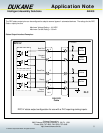
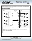
Status Output Signal Descriptions:
Bad Part Output – (J602 pin 3) This status output will activate when the data acquired during the welding sequence
exceeds one of the user defined boundaries within the Bad Part Limits portion of the user setup.
Please refer to the Process Limits section of the DPC IV manual for further details on selecting
and setting up a Bad Part Limit window.
Good Part Output - (J602 pin 5) This status output will activate when the data acquired during the welding sequence
does not exceed any of the user defined boundaries within the Bad Part Limits portion of the user
setup. Please refer to the Process Limits section of the DPC IV manual for further details on
selecting and setting up a Bad Part Limit window.
Suspect Part Output - (J602 pin 4) This status output will activate when the data acquired during the welding sequence
exceeds one of the user defined boundaries within the Suspect Part Limits portion of the user
setup. Please refer to the Process Limits section of the DPC IV manual for further details on
selecting and setting up a Suspect Part Limit window.
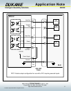
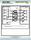
In Cycle (J602 pin 4 redefined) - This status output will activate when the welding cycle begins. If
the status outputs have been set for maintained, In Cycle will deactivate when the Hold portion of
the welding cycle has completed. Please refer to the Hardware Setup section of the DCP IV
manual for further details on redefining J602 pin 4.
Sonics On (J602 pin 4 redefined) – This status output will activate when the DPC produces the
ultrasound welding signal that creates motion in the transducer stack assembly. Activation of this
signal will occur during the Weld, Scrub, and Afterburst portions of the weld cycle. Please refer to
the Hardware Setup section of the DCP IV manual for further details on redefining J602 pin 4.
In Hold (J602 pin 4 redefined) – This status output will activate when the DPC is processing the
Hold portion of the welding cycle. Please refer to the Hardware Setup section of the DCP IV
manual for further details on redefining J602 pin 4.
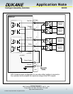
Ready Output - (J602 pin 6) This status output will activate at the completion of the Hold portion of the welding
sequence. It should be noted that the activation of the Afterburst feature and the return of the
pneumatic press to the home position will occur after the activation of the Ready Output status
signal. Please refer to the Process Control section of the DPC IV manual for further information
on the activation and use of the Afterburst feature. In addition please refer to the Hardware Setup
section of the DCP IV manual for further details on redefining J602 pin 6.
Network Active (J602 pin 6 redefined) – This status output will activate when the DPC is an active
node on a DPC network. Please refer to the Network section of the DPC IV manual for further
details on setting up a DPC network. Please refer to the Hardware Setup section of the DCP IV
manual for further details on redefining J602 pin 6.
Sonics On (J602 pin 6 redefined) – This status output will activate when the DPC produces the
ultrasound welding signal that creates motion in the transducer stack assembly. . Please refer to
the Hardware Setup section of the DCP IV manual for further details on redefining J602 pin 6.