


- 3 -
33103
D
U
K
A
N
E
A
A
p
p
p
p
l
l
i
i
c
c
a
a
t
t
i
i
o
o
n
n
N
N
o
o
t
t
e
e
AN400
© Dukane Corporation 2004. All rights reserved.
Dukane Corporation
2900 Dukane Drive Saint Charles, IL 60174 USA
Phone (630) 797-4900 FAX (630) 797-4949
http://www.dukane.com/us
Intelligent Assembly Solutions
3
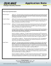
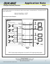
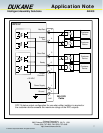
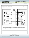
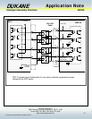
Status Output signals for the J602 Connector:
There are four status output signals available on the J602 connector. Each of these outputs are driven by a solid state
relay that creates a switch closure between the specified output pin and the Output Common pin. These pins can be
configured within the DPC software menus to provide a signal that accommodates the requirements of most automation
interface equipment. The available configurations for these output signals are:
Active High Outputs – This setting will produce a closed switch condition between the specified output pin and
the Output Common pin when the output signal is activated. (Factory default setting)
Active Low Outputs - This setting will produce an open switch condition between the specified output pin and
the Output Common pin when the output signal is activated.
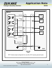
Maintained Outputs - This setting will produce an output signal that is maintained from the completion of a
welding cycle until the beginning of the next welding cycle activation. (Factory default
setting)
Pulsed Outputs - This setting will produce an output signal that is pulsed a single time for 100 mS as the
end of the welding cycle.
Note: Please refer to the Hardware menu section of the DPC IV manual for further information on these features.
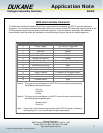
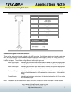
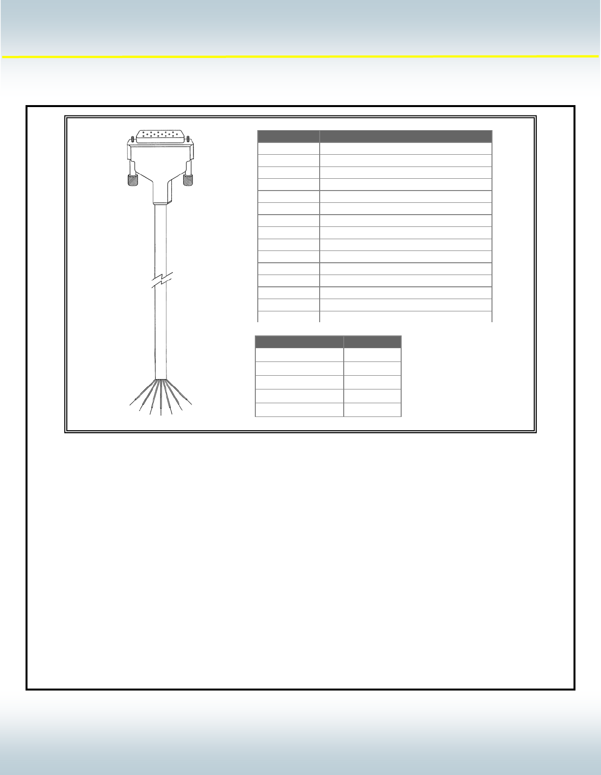
Part Number Length
200-1203 10 FT
200-1203-15 15 FT
200-1203-20 20 FT
200-1203-25 25 FT
200-1203-30 30 FT
Pin # Conductor Color
1 Red
2 Black
3 Blue / Black
4 Green / White
5 Blue / White
6 Red / Black
7 White / Black
8 White
9 Orange
10 Blue
11 Orange / Black
12 Red / White
13 Green Black
14 Black / White
15 Green