


- 8 -
88108
D
U
K
A
N
E
A
A
p
p
p
p
l
l
i
i
c
c
a
a
t
t
i
i
o
o
n
n
N
N
o
o
t
t
e
e
AN400
© Dukane Corporation 2004. All rights reserved.
Dukane Corporation
2900 Dukane Drive Saint Charles, IL 60174 USA
Phone (630) 797-4900 FAX (630) 797-4949
http://www.dukane.com/us
Intelligent Assembly Solutions
8
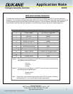
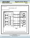
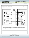
System Input signals for the J602 Connector:
There are four system input signals available on the J602 connector. Each of these inputs are configured as sinking
inputs ( Do not apply voltage to the J602 inputs).
Automation Input - (J602 pin 8) This system input signal is activated by an external dry contact closure to the DPC
Ground pin on J602 pin2). The minimum duration for the activation of this input is 100 mS. The
maximum duration of this input is determined by the duration of the weld cycle. This input should
be deactivated before the end of the weld cycle to avoid an error condition (Associated Error: #
212 Auto Active at Cycle Start). Please refer to the Initiate Mode section of the DPC IV manual
for details on the activation and use of the Auto Initiate mode.
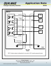
Automation Stop N/O- (J602 pin 9) This system input signal is activated by an external dry contact closure to the DPC
Ground pin on J602 pin2). The minimum duration for the activation of this input is 100 mS.
Activation of this input will end the welding cycle and deactivate all valves in the press. This
system response will continue until the contact closure to the DPC ground is removed. Weld
cycles that have been stopped due to the activation of this input will not be counted in the part
count value displayed on the DPC. Please refer to the Initiate Mode section of the DPC IV
manual for details on the activation and use of the Automation Stop mode (Auto Abort).
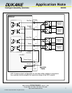
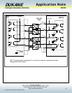
Automation Stop N/C- (J602 pin 10) This system input signal is activated by an removing an external dry contact closure
to the DPC Ground pin on J602 pin2). The minimum duration for the activation of this input is 100
mS. Activation of this input will end the welding cycle and deactivate all valves in the press. This
system response will continue until the contact closure to the DPC ground is replaced. Weld
cycles that have been stopped due to the activation of this input will not be counted in the part
count value displayed on the DPC. Please refer to the Initiate Mode section of the DPC IV
manual for details on the activation and use of the Automation Stop mode (Auto Abort).
Hand Probe Press Inhibit - (J602 pin 11) This system input is activated by an external dry contact closure to the DPC
Ground pin on J602 pin2). The minimum duration for the activation of this input is 100 mS.
Activation of this input is intended to configure the DPC for a probe system functionality. It will
deactivate all valves for the press during a welding cycle. This system response will continue until
the contact closure to the DPC ground is removed.