


15
ADJUSTING HEIGHT
OF INFEED ROLLER
The infeed roller is adjusted at the factory at 0.040"
below the cutting circle. To check and adjust the
height of the infeed roller, proceed as follows:
DISCONNECT MACHINE FROM POWER
SOURCE.
1. Make sure the knives are adjusted properly as ex-
plained under “CHECKING, ADJUSTING AND RE-
PLACING KNIVES.”
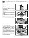
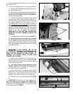
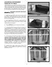
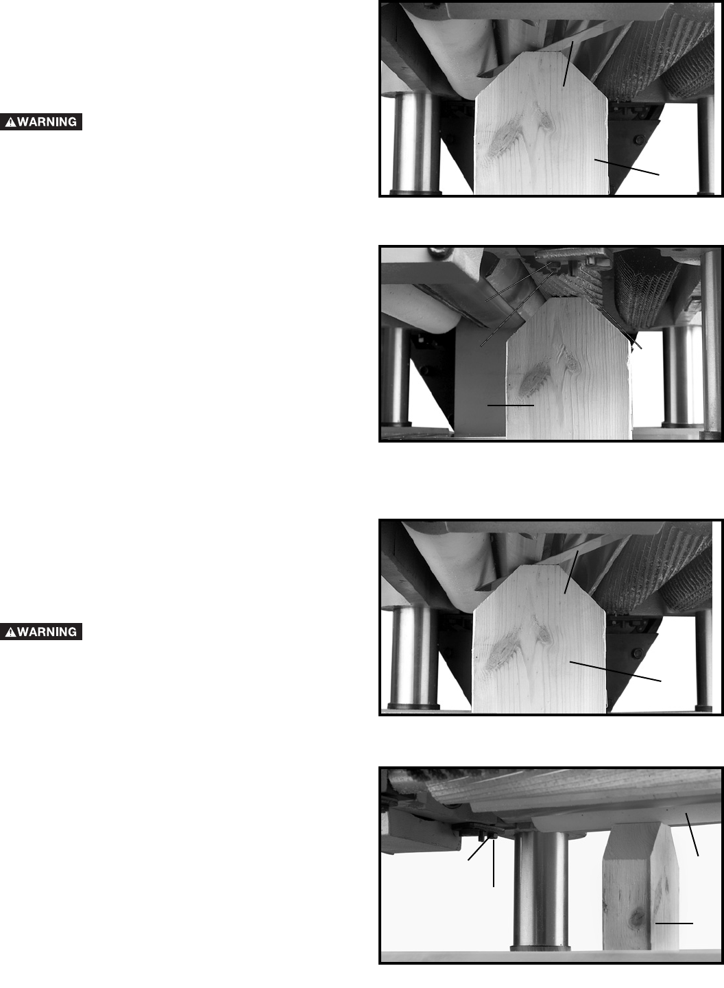
2. Place the gage block (A) Fig. 42, on the table directly
underneath the cutterhead, as shown. Using a 0.040"
feeler gage (B) placed on top of the gage block, raise or
lower the head assembly until one of the knives just
touches the feeler gage when the knife is at its lowest
point. Then tighten the head locking knobs.
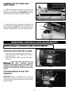
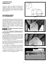
3. Move the gage block (A) Fig. 43, minus the feeler
gage, under one end of the infeed roller (C). The bottom
of the infeed roller (C) should just touch the top of the
gage block (A), as shown.
4. If the height of the infeed roller must be adjusted,
loosen nut (D) Fig. 43, and turn adjusting screw (E) until
that end of the infeed roller just touches the top of the
gage block. Then tighten nut (D).
5. Repeat this adjustment with the gage block on the
opposite end of the infeed roller.
Fig. 42
Fig. 43
Fig. 44
Fig. 45
ADJUSTING HEIGHT
OF OUTFEED ROLLER
The outfeed roller is adjusted at the factory to be 0.040"
below the cutting circle. To check and adjust the
height of the outfeed roller, proceed as follows:
DISCONNECT MACHINE FROM POWER
SOURCE.
1. Make sure the knives are adjusted properly as ex-
plained under “CHECKING, ADJUSTING AND RE-
PLACING KNIVES.”
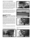
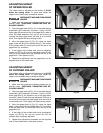
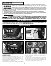
2. Place the gage block (A) Fig. 44, on the table directly
underneath the cutterhead, as shown. Using a 0.040"
feeler gage (B) Fig. 44, placed on top of the gage block
as shown, raise or lower the head assembly until one of
the knives just touches the feeler gage when the knife is
at its lowest point. Then tighten the head locking knobs.
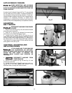
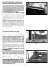
3. Move the gage block (A) Fig. 45, minus the feeler
gage, under the end of the outfeed roller (C). The bottom
of the out-feed roller (C) should just touch the top of the
gage block (A).
4. If the height of the outfeed roller must be adjusted,
loosen nut (D) Fig. 45, and turn screw (E) until the
outfeed roller is properly adjusted.
5. Repeat this adjustment procedure on the opposite
end of the outfeed roller in the same manner.
B
A
D
E
A
C
B
A
C
A
D
E