


19
ENGLISH
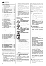
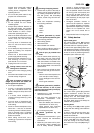
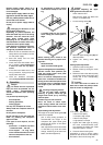
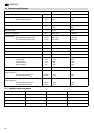
Rip fence
The rip fence (33) is clamped to the
front. The rip fence can be used on both
sides of the blade.
A
Danger!
Start the saw only after the fol-
lowing preparations have been com-
pleted:
− the saw is fastened;
− the saw table is installed and
aligned;
− the V-belt tension checked;
− the combination switch/plug is
installed;
− the safety devices have been
checked.
Connect the saw to the mains supply
only after all of the above prepara-
tions are completed! Otherwise there
is a risk of an unintentional starting of
the saw, which may cause severe per-
sonal injury.
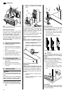
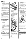
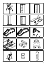
7.1 Mounting
For a firm stand the saw must be
mounted on a stable supporting surface:
1. Drill four holes in the supporting sur-
face.
2. Put fixing bolts through the base
plate and secure with nuts.
Optimal working height and stability is
provided by the workstand (optional
accessory), which is already prepared
for mounting the saw.
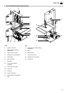
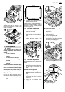
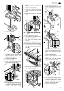
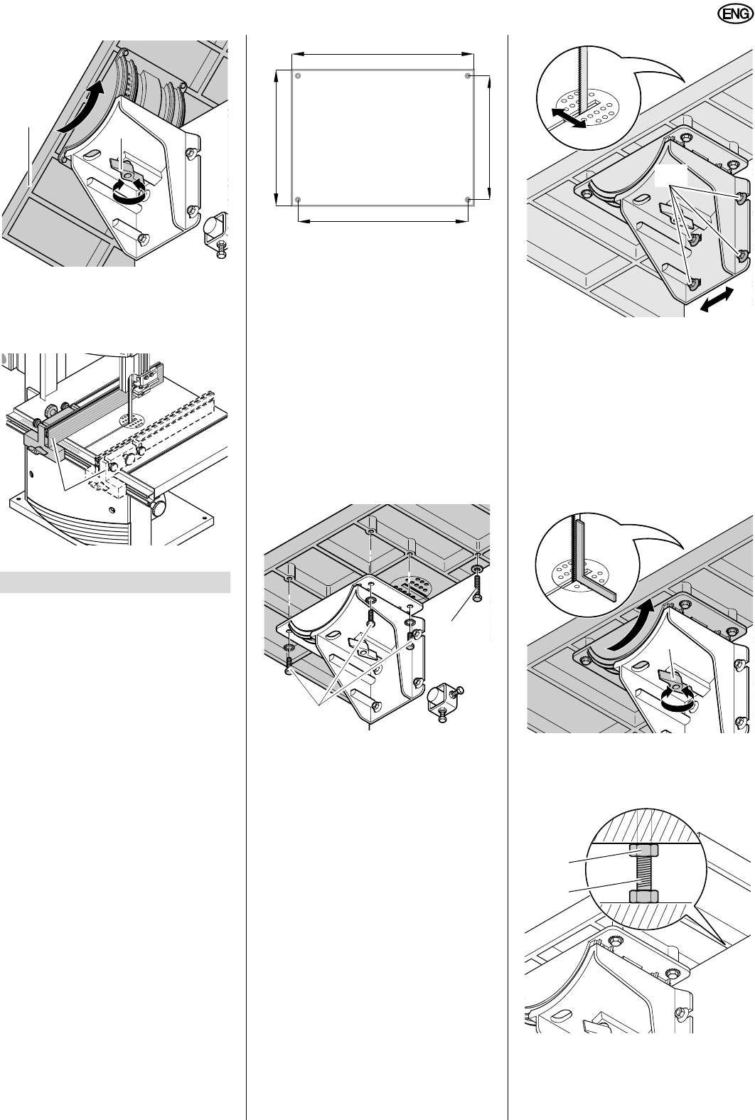
7.2 Saw table installation
1. Fit limit stop screw (34) to the under-
side of the saw table.
2. Guide saw table over the band saw
blade and place it on the table trun-
nion.
3. Attach the saw table with four each
screws (35) and washers to the
table trunnion.
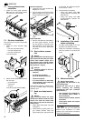
7.3 Saw table alignment
The saw table needs to be aligned in two
planes
− laterally, in order for the blade to run
dead centre through the table insert;
− at right angles to the band saw
blade.
Saw table lateral alignment
1. Loosen the four fastening screws
(36) that hold the lower table trun-
nion.
2. Align saw table so that the blade
runs through the centre of the table
insert's slot.
3. Tighten the four fastening screws
(36) again.
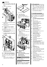
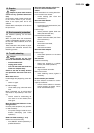
Aligning the saw table at right angles
to the band saw blade
1. Raise upper blade guide fully (see
“Operation”).
2. Check band saw blade tension (see
“Initial operation”).
3. Loosen locking screw (37).
4. Using a try square, set the table at
right angles to the blade and tighten
the locking screw (37) again.
5. Loosen locking nut (38) and adjust
limit stop screw (39) until it touches
the saw housing.
6. Tighten locking nut.
7. Initial operation
31
32
33
428 mm
312 mm
458 mm
342 mm
34
35
36
37
39
38