


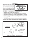
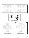
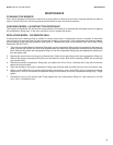

Keep 1/4 inch (6 mm) clearance between electrodes
and piping. The electrodes must be completely sub-
merged in the process liquid, i.e., to the level of the
threaded connection. See Figure 1 for recommended
orientation.
If the sensor is installed in a side stream with the
sample draining to open atmosphere, bubbles may
accumulate on the electrodes. Trapped bubbles will
cause errors. As bubbles accumulate, the conduc-
tivity reading drops. To control bubble formation,
apply a small amount of back pressure to the drain.
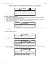
MODEL 140,141, and 142 sensors INSTALLATION
INSTALLATION
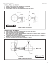
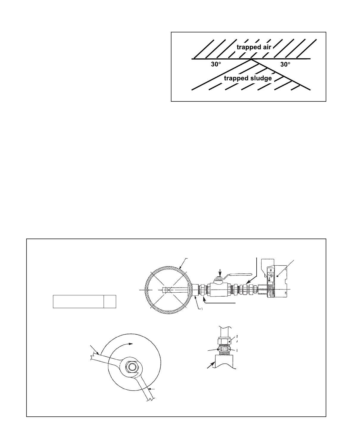
INSTALLATION – 140 SENSOR WITH BALL VALVE KIT (PN 23724-00)*
1. Install the sensor in either a 1-inch NPT weldalet or in a 1-inch pipe tee.
2. Remove the plastic shipping cap from the sensor.
3. Screw the 1-inch hex nipple into the weldalet or pipe tee. See Figure 2. Use pipe tape on the threads.
4. Position the sensor for easy access to the ball valve handle, sensor compression fitting nut, and junction box.
5. Make sure the ball valve is in the fully open position.
6. Finger tighten the sensor compression fitting nut. Do not over tighten because the next step is to press the
sensor into the process pipe.
7. Insert the sensor tube until the sensor tip is no closer than 1 inch (25 mm) from the far wall of the process
pipe. See Figure 2.
8. Tighten the sensor compression fitting nut to hold the sensor tip in position. See Figure 2 for instructions.
*If the ball valve assembly is already in place and the process line is pressurized, refer to Inserting the 140
Sensor Section on page 6.
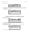
A
PROCESS PIPING
PUT WRENCH “A” HERE AND
TURN
WRENCH “A”
WRENCH “B”
BALL VALVE
SENSOR COMPRESSION
FITTING
SENSOR
PUT WRENCH “B” HERE
SIDE VIEW
TOP VIEW
CAUTION
Process O-Ring
must be in place
and is critical.
Replace if worn
or dirty.
Tighten finger tight before
inserting sensor
Hold body with wrench
B and turn WRENCH A
1 1/4 turns beyond fin-
ger tight.
WELDALET
1-in. NPT HEX NIPPLE
BALL VALVE
DWG. NO. REV.
40014008 E
FIGURE 2. Installing model 140 sensor with ball valve kit (PN 23724-00).
°
°
FIGURE 1. Sensor Orientation
2