


3
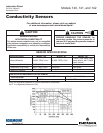
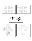
MODEL 140,141, and 142 sensors INSTALLATION
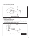
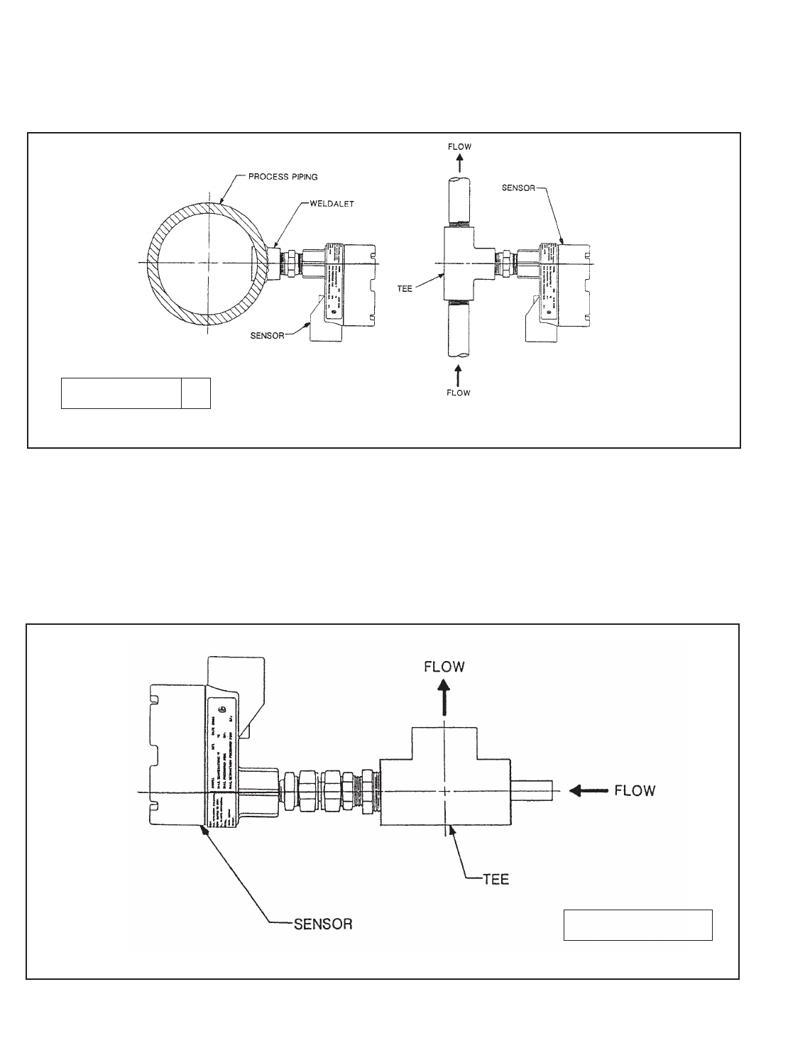
FIGURE 3. Installing model 141 sensor
DWG. NO. REV.
40014204 B
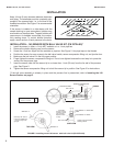
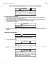
INSTALLATION – 141 SENSOR
1. Install the sensor in a 3/4-inch NPT weldalet or in a 1-inch pipe tee.
2. Remove the plastic shipping cap from the sensor.
3. Screw the sensor into the fitting. Use pipe tape on the threads. See Figure 3.
INSTALLATION – 142 SENSOR
1. Install the sensor in a 3/4-inch NPT weldalet or in a 1-inch pipe tee. See Figure 4.
2. Remove the plastic shipping cap from the sensor.
3. Screw the sensor into the fitting. Use pipe tape on the threads. DO NOT tighten the sensor compression
fitting until the sensor is correctly positioned.
4. If necessary, loosen the sensor compression fitting and position the sensor so that the tip of the sensor is
at least 1-inch (25 mm) from the far wall of the pipe.
5. Tighten the compression fitting using the procedure shown in Figure 2.
DWG. NO. REV.
40014204 B
FIGURE 4. Installing model 142 sensor