


RTD
RTD in
RTD sense
RTD return
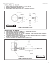
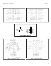
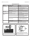
MODEL 140,141, and 142 sensors WIRING
WIRING
All 140 series sensors have a junction box mounted on the back of the sensor. Wiring connections in the junction box
are shown in Figure 5.
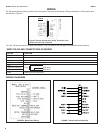
Figure 5. Sensor junction box wiring. Terminals in the
junction box are not numbered.
GRAY
GRAY
MODEL 140 SERIES
141 and 142 sensors have one gray wire (shown). The 140 sensor has two gray wires attached to the terminal.
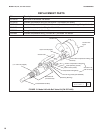
WIRE COLOR AND CONNECTIONS IN SENSOR
COLOR FUNCTION
Gray Connects to outer electrode
Clear Coaxial shield for gray wire
Orange Connects to inner electrode
Clear Coaxial shield for orange wire
Red
White with red stripe
White
Clear Shield for all RTD lead wires
CABLE
9
8
7
6
5
4
3
2
1
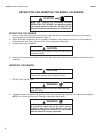
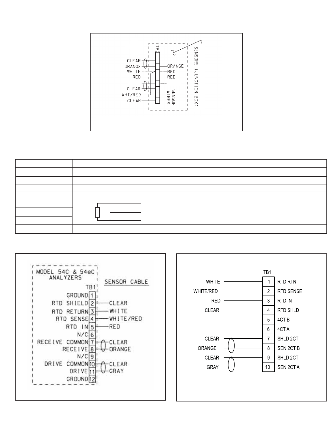
FIGURE 6. Model 54eC Wiring
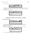
FIGURE 7. Model 1056 and 56 Wiring
WIRING DIAGRAMS
4