


Section
4
Installation
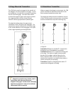
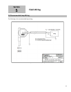
4.0 Gage Mount Installation
The LTM-Series can be mounted to the side of a
Magtech LG series level gage using special mounting
brackets and stainless steel hose clamps. When
mounting the transmitter to an LG series gage the
active sensor region of the probe should fall within
the centerline of the process connections on the
gage. If the transmitter’s deadband region is inside
the centerline of the process connections the
transmitter will not output an accurate
measurement because the active region of the
probe is too short. When placing an order for a
transmitter to accompany an existing gage it is
important to indicate the style of the gage, the
temperature, and the center-to-center dimension.
Calibration of the probe is factory set to the
center-to-center dimensions provided
; however a
re-ranging may have to be performed to match the
probe to the desired control room specifications.
See Section 7.1 “Change Range” for more details.
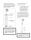
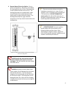
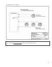
4.1 Standalone Installation
The LTM-Series standalone transmitter comes
equipped with a ¾” mnpt compression fitting,
mounted approximately 3 to 6 inches below the
electronics housing. The fitting is placed in this area
to ensure the transmitter is calibrated in the sensor
tubes active region. Refer to the standalone
drawings for a visual description of the transmitter
features. Optional configurations are available
upon request (2” mnpt, flanges, etc…). The
magnetic float used in the stand-alone unit is
designed to travel up the sensor tube with the
change in fluid level. If build-up of process or
contaminates should restrict the movement of the
float, the transmitter sensor tube will have to be
cleaned or the float may have to be replaced with
one that has a larger inside diameter. The floats are
designed to match the pressure and specific gravity
for the process being measured and come in various
materials ranging from stainless to kynar. The
magnetic float can be changed out at any time to
accommodate the processes being measured. The
float stop, located at the bottom of the
transmitters, can be removed to allow the float to
slide off the sensor tube.
4.2 General Installation Guidelines
The basic steps to installing the LTMs are:
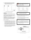
1. Inspection of equipment: Inspect the parts
that are listed on the packing slip. Make sure
nothing appears to be damaged such as a
broken glass from the level indicator assembly
(flippers), damaged float, or a damaged
transmitter. Please file a claim with the
shipping company immediately if it is believed
the shipment has arrived damaged and be
prepared to provide pictures.
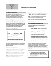
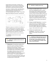
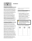
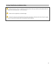
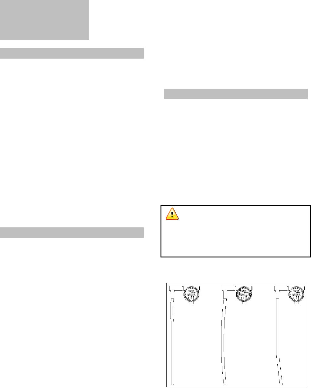
The sensor probe of the transmitter
SHOULD NOT BE BENT, BOWED, OR KINKED in
any way or the transmitter will not work (will
most likely go into fail mode).
The following is a depiction of damaged probes:
Figure 8. All damaged sensor probes
7