


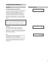

2. Water damage to the electronics module or
sensor probe. This is potentially the most
severe case the symptoms are unpredictable. If
there is any suspicion that the transmitter may
have incurred water damage please contact the
factory to make arrangements to have the unit
sent back for factory inspection.
Physical and water damage are not
covered under warranty.
3. Magnetic Indentation. It is possible for any
magnetostrictive instrument to have residual
magnetic energy stored along the length of the
waveguide. These magnetic anomalies can
interfere with the output response signal. If
this appears to be the case a level gage float (or
a bar magnet preferably) may be run along the
length of the sensor tube, past the head of the
transmitter, in an even motion without
stopping. This will usually clear all such
magnetic anomalies.
Never move a magnet in perpendicular
motion away from the sensor tube. This will
always leave a residual magnetic field in the
waveguide which causes the transmitter
output to be erroneous or unstable.
The LTM-350 is HART compatible, however
HART communication will not work if the unit
is not powering up.
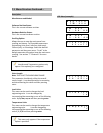
8.2 Power Supply Troubleshooting
The LTM-250/350 is designed to operate with a
supply voltage of 13 – 36 Vdc (minimum 13V @
20mA) across its terminal without affecting the
analog current output. The most common supply
voltage used is 24Vdc.
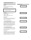
At times additional resistance in the loop is
necessary, either in the form of a second load
resistor or higher resistance safety barrier. This will
appear to limit the maximum output of the
transmitter to below 20mA. The transmitter will
perform correctly up to a certain point. To resolve
this problem, the voltage of the loop supply must
be increased. Even a slight adjustment of 1Vdc may
be sufficient.
All connections must be checked for improper
wiring or polarity before power is applied. LTM-
Series transmitters are polarity protected.
8.3 General Troubleshooting
Below are some troubleshooting procedures for the
LTM transmitters that have been established
overtime.
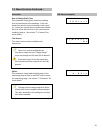
Symptom: Transmitter is not powering up.
The LCD is not turning on.
Resolutions:
1. Make sure power is applied correctly (meaning
plus and minus are not reversed). The
transmitter is polarity protected.
2. Make sure the electronics module is seated
properly. Open the front cover (where the LCD
is) and firmly push on the “Magtech” text. A
good way to tell if the electronics are not
seated properly is by making sure the
protection screws are not physically higher than
the outside of the housing. Sometimes pulling
the electronics module out and putting it back
in can reseat the electronics correctly. Use
cutters or needle nose pliers to grip the
protection screw and lightly pull on each screw
(alternate).
29